Today, let’s talk about how to interface with Omron PLC via Hostlink protocol.
Het artikel dat we eerder bespraken:
Hoe EG edge computing gateway integreren met General Electric PLC
Integratie met Xinjie PLC via Modbus RTU-protocol
Interface met Keyence KV-8000 serie PLC's via het MC-3E protocol
Hoe te communiceren met Keyence KV-7500 serie PLC's via het KV TCP-protocol
Interface met Panasonic PLC's via het Mewtocol TCP-protocol
Interface met Inovance PLC via Modbus RTU-protocol
Interface met AB PLC via PCCC-protocol
How to interface with AB PLC via EtherNet/IP protocol
How to interface with Omron PLC via EtherNet/IP protocol
1. Hardwareverbinding
Compatible PLC: CP Series
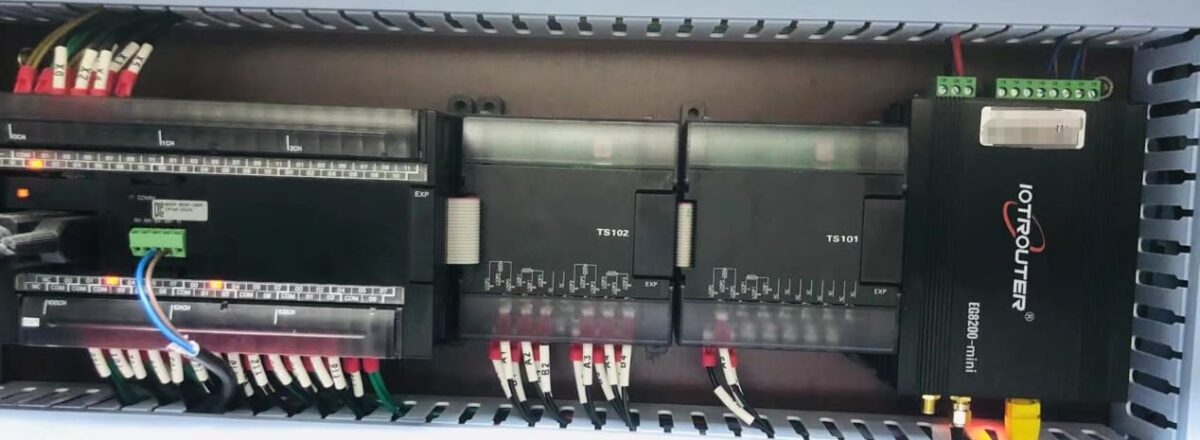
The Hostlink protocol uses serial communication. For this example, the PLC model CP1W-0026 uses RS485 communication. Simply connect the PLC’s 485 interface SDA- to the gateway’s B1 pin, and the PLC’s 485 interface SDB+ to the gateway’s A1 pin.
2. PLC Serial Parameters
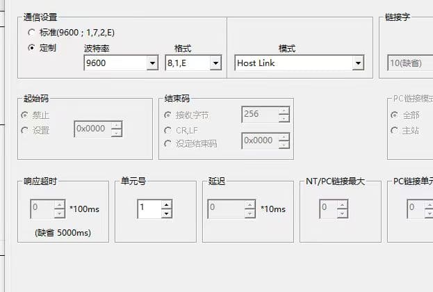
Note the unit number (station number 1) and baud rate (9600-8-1-E). These parameters will be required for subsequent gateway configuration.
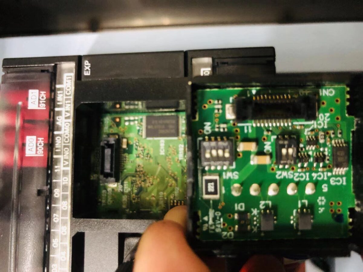
Note: DIP Switch Settings: 1 and 4 (OFF), 2, 3, 5, 6 (NO)
3. Gateway Configuration
3.1. PLC Connection Setup
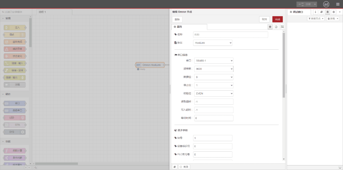
Drag an Omron node from the left panel. Double-click to open the settings page and configure based on the PLC’s serial parameters as follows:
Protocol: Select HostLink
Serial Port: Select RS485-1 (based on actual hardware connections)
Baud Rate: 9600
Data Bits: 8
Stop Bits: 1
Parity: EVEN
Station Number: 1
3.2. Configuratie gegevenspunt
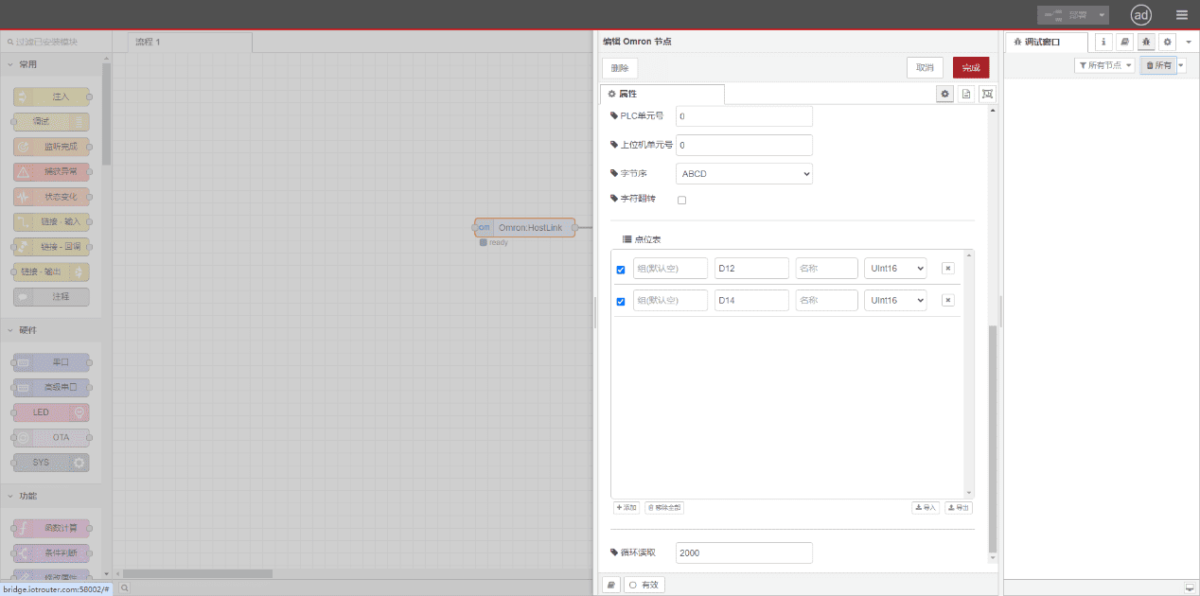
Enter the data points to be read in the Omron node’s parameter list. Once configured, the PLC data will be automatically retrieved at the set frequency. Data points are typically provided by PLC engineers. After obtaining the point list, enter data points in the format required by the gateway. For specific correspondence, refer to:(Je kunt Google Chrome gebruiken voor vertaling) https://iotrouter.yuque.com/zn3vdn/eg8000/skfapgdm7332it5q
In the parameter list, fill in Address/Name/Data Type/Data Length sequentially. Set a 2-second cycle for periodic reading, as shown in the figure:
3.3. Testen
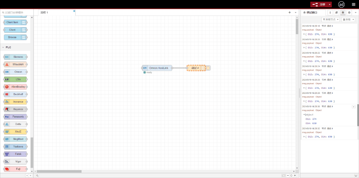
Click Deploy. Observe that a data point is printed every 2 seconds. Verify that the output value matches the actual value. Communication successful!
