This guide explains how the EM300 Industrial Edge Controller works as an IEC104 Client gateway to connect existing field devices with IEC104 Server systems for data acquisition and remote control — without PLC programming.
Introduction
Most substation and plant-monitoring builds hit the same wall: the SCADA or control system on the upper layer speaks IEC 60870-5-104, while the meters, RTUs and small PLCs on the floor speak Modbus RTU/TCP, DL/T645, BACnet or CJ188. None of them speak IEC104 natively, so the usual fix is either a dedicated IEC104 protocol converter or a block of PLC logic written just to bridge the two.
The EM300 industrial edge controller provides a simpler approach. Configured as an IEC104 Client gateway, it connects existing field devices with IEC104 Server systems and completes IEC104 integration through configuration instead of custom PLC code.
What “IEC104 Client” Means Here
IEC 60870-5-104 defines two communication roles: Client and Server. In many industrial systems, the Client actively initiates communication, while the Server responds to requests.
| Role | What it does |
|---|---|
| IEC104 Server | Provides data and responds to requests from the client |
| IEC104 Client | Establishes communication, reads data, sends commands |
So the EM300 is the active side:
Field devices                 EM300                 IEC104 Server

(Modbus PLC / meter)  →  IEC104 Client  →     (control system)
As the IEC104 Client, EM300 establishes the communication session with the IEC104 Server and supports functions such as interrogation and clock synchronization.
Why Run the IEC104 Client Gateway on EM300
1. It bridges the protocols you already have
Field devices are usually not replaced just because a control system adopts IEC104. A power meter may still communicate through Modbus TCP, an older RTU may use Modbus RTU, and a building controller may rely on BACnet.
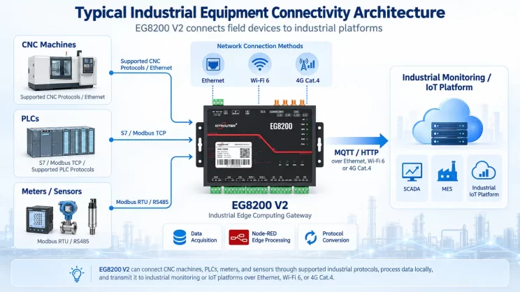
EM300 bridges this communication gap by collecting data from these existing devices and communicating with the IEC104 Server as an IEC104 Client. This allows legacy equipment to be integrated into IEC104 systems without changing the devices already deployed in the field.
2. No PLC programming
Traditional solutions often require PLC programming to handle IEC104 communication. Engineers need to write and maintain communication logic, define data mapping, and manage connection status and recovery processes.
With EM300, the integration process is much simpler. Engineers only need to configure the IEC104 connection, define the required points, and deploy the workflow through the visual programming environment. IEC104 communication is handled directly by EM300 without additional PLC development.
3. You can both read and command
An IEC104 Client gateway is not only used for data acquisition. EM300 supports both data acquisition and remote control functions:
Reading
- Single point information
- Double point information
- Normalized measurement values
- Scaled measurement values
- Short floating-point measurement values
- Counter values
Control
- Single point commands
- Double point commands
- Step regulation commands
- Set-point commands (normalized, scaled, floating-point, 32-bit bit string)
In addition, EM300 supports general interrogation, counter interrogation, and clock synchronization through the IEC104 Client configuration and injection objects.
A Real Architecture: Renewable Energy Monitoring
A typical renewable energy monitoring system may include solar controllers, energy meters, and other field devices that communicate through Modbus RTU/TCP. EM300 collects data from these devices and exchanges it with IEC104 Server systems as an IEC104 Client.
Through EM300, existing field equipment can be integrated into IEC104-based control systems without replacing devices or adding additional protocol converters.
Quick Start: Configure EM300 as an IEC104 Client
Preparation
Before configuration, make sure:
1. The engineer knows the target IEC104 Server/Slave IP address and port (default: 2404).
2. The engineer has the required point information for data acquisition.
3. The edge gateway is connected to the same local network as the IEC104 Server/Slave.
Configure the Gateway
1. Configure the gateway network settings according to the Quick Start Guide.
2. Enter the Node-RED Visual Programming environment.
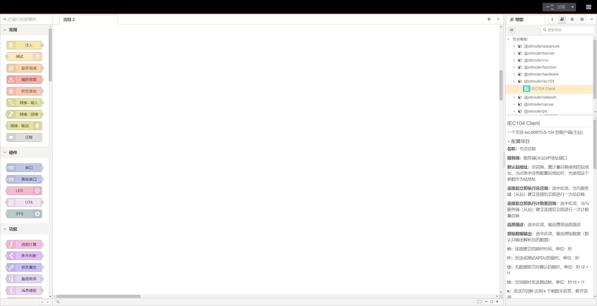
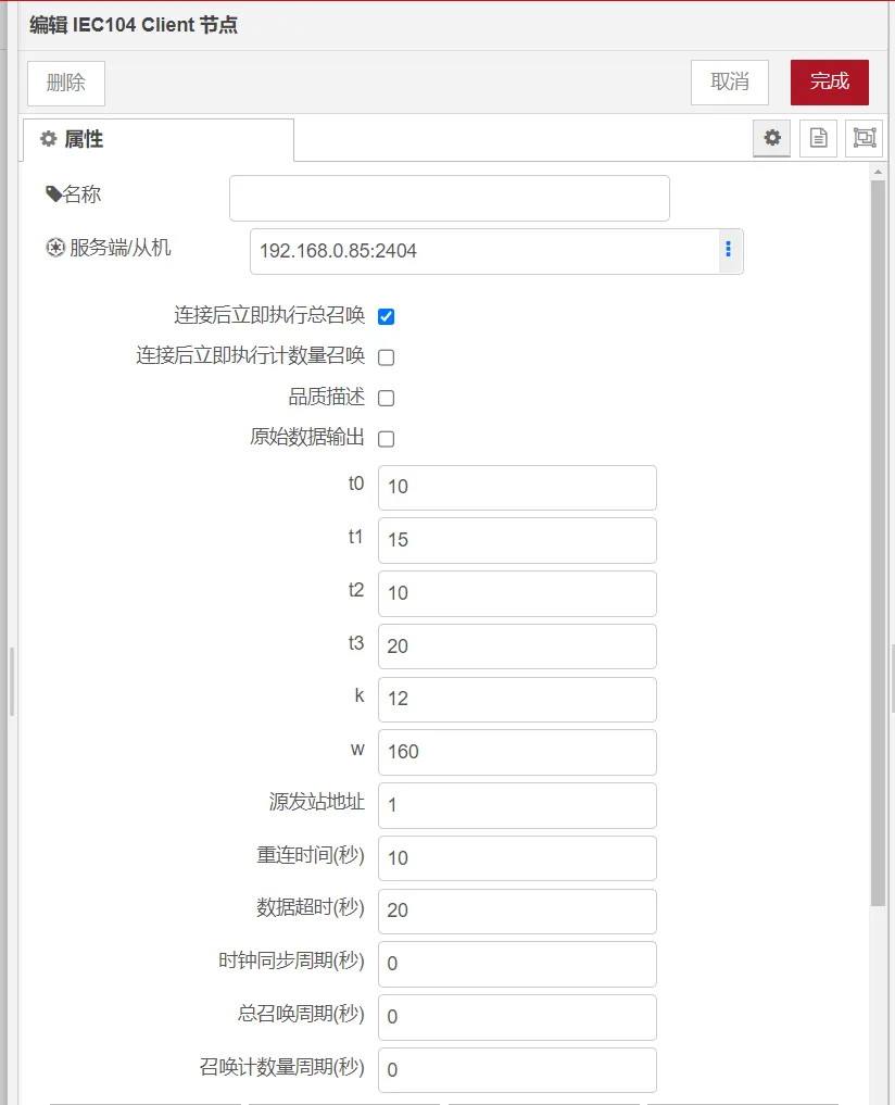
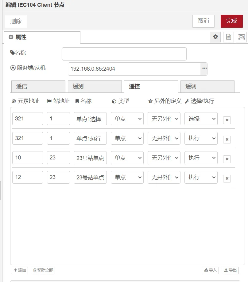
3. Select the IEC104 Client node and configure the IP address, port, connection parameters, and point table.
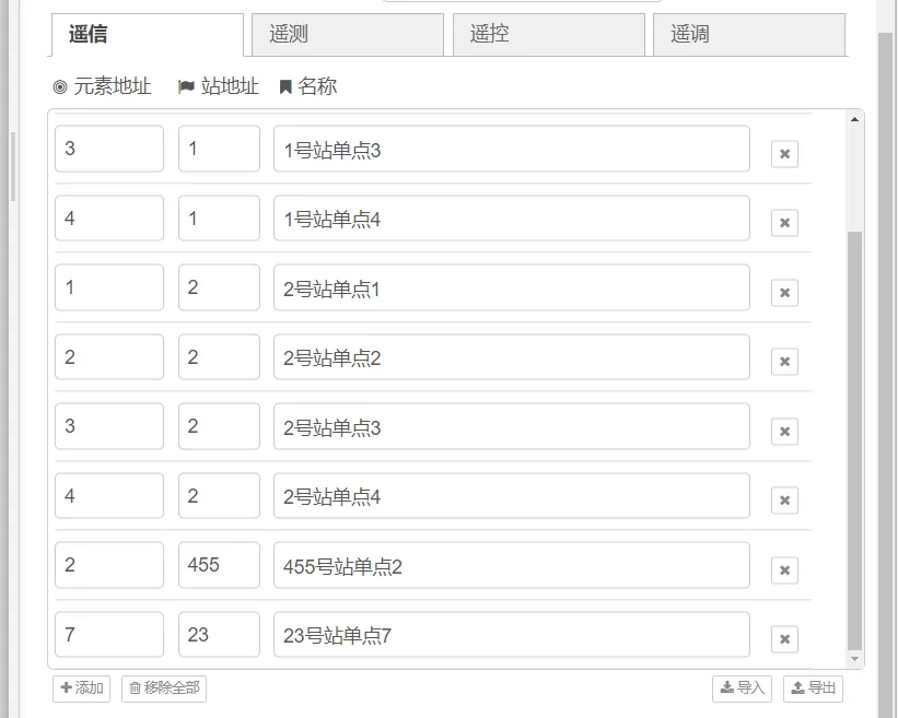
4. Deploy the workflow.
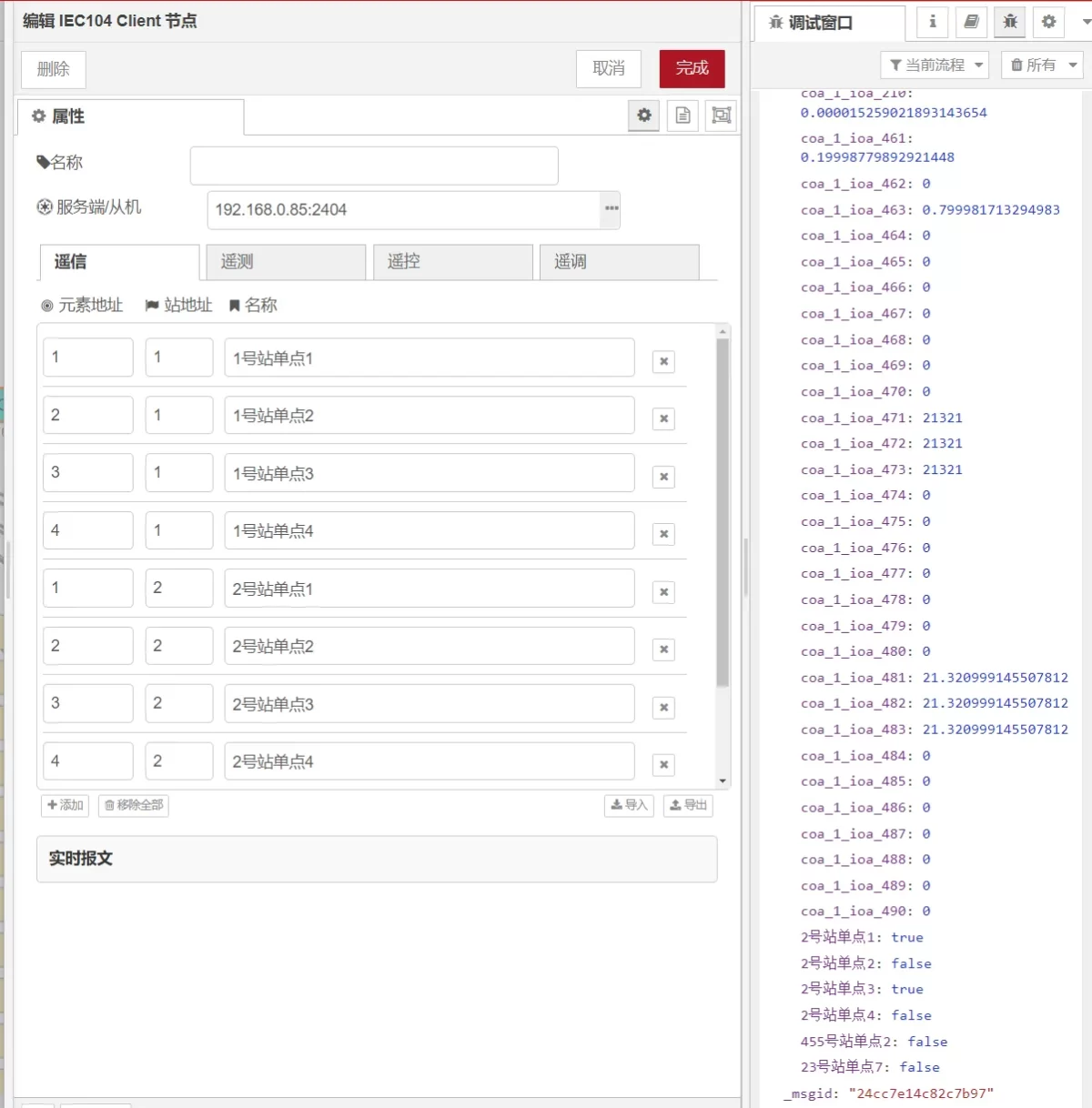
5. Configure the points required for remote control and set-point operations.
6. Perform external injection testing.
6.1 Before injection, check that the variable value on the IEC104 Server is False.

6.2 Send the remote control command according to the configured injection message.
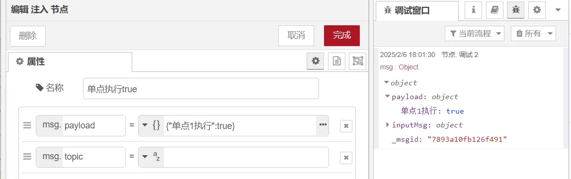
6.3 After injection, check that the variable value on the IEC104 Server changes to True.

IEC104 Client Configuration Parameters
| Parameter | Description |
|---|---|
| Name | Node name displayed in the workflow |
| Server/Slave | IP address and port of the IEC104 Server/Slave |
| General Interrogation after connection | When enabled, performs general interrogation immediately after establishing a connection with the IEC104 Server/Slave |
| Counter Interrogation after connection | When enabled, performs counter interrogation immediately after establishing a connection |
| Float formatting | Number of decimal places retained for floating-point values |
| t0 | Connection establishment timeout (seconds) |
| t1 | APDU send/test timeout (seconds) |
| t2 | Acknowledgement timeout when no data messages are received (t2 < t1) |
| t3 | Idle timeout for sending test frames (t3 > t1) |
| k | Maximum number of unacknowledged I frames before disconnecting |
| w | Number of received messages before sending an S frame |
| Source station address | Current node address |
| GI station address | Station address used for general interrogation and counter interrogation |
| Reconnection time | After t0 timeout occurs, wait for this period before reconnecting |
| Data timeout | Maximum waiting time for responses from the IEC104 Server/Slave |
| Clock synchronization period | Interval for sending clock synchronization commands |
| General interrogation period | Interval for sending general interrogation commands |
| Counter interrogation period | Interval for sending counter interrogation commands |
IEC104 Client vs IEC104 Server
| IEC104 Client | IEC104 Server | |
|---|---|---|
| Connection | Opens the link | Waits for a link |
| Data | Sends requests | Sends responses |
| Control | Issues commands | Executes commands |
| Interrogation | Starts it | Answers it |
| Used for | Field device integration | Providing data to IEC104 clients |
EM300 can run either role. When integrating field devices into IEC104 systems, the Client role is typically used to communicate actively with the IEC104 Server.
Why EM300 for the Job
Interfaces:
4× isolated RS485, digital I/O, Ethernet, 4G, Wi-Fi
Protocols:
Modbus RTU/TCP, IEC104 Client & Server, MQTT, BACnet, DL/T645
Edge capabilities:
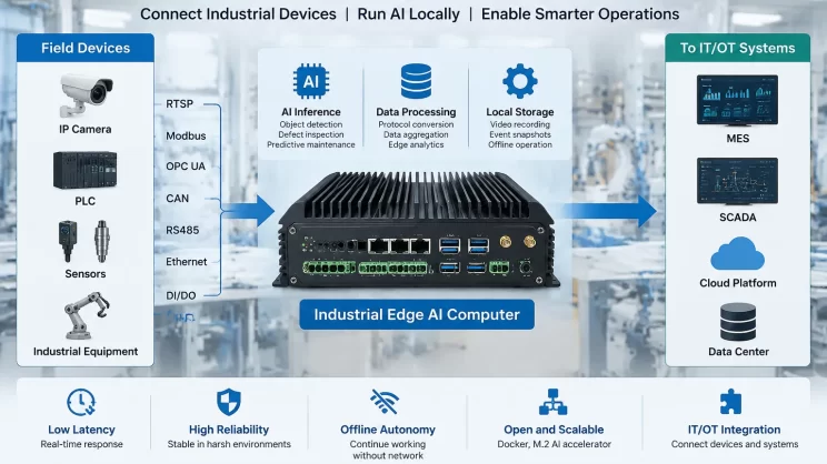
Local data handling, Node-RED visual programming, flexible workflow configuration, remote maintenance
Industrial reliability:
−40 °C to +85 °C operating range, watchdog protection
Where It Gets Used
Smart grid: Power meter → EM300 → IEC104 Server
Renewable energy: Energy controller → EM300 → IEC104 Server
Industrial power monitoring: Factory meter → EM300 → central monitoring
FAQ
Q1: What’s the difference between an IEC104 client and a server?
A1: The IEC104 Client establishes communication and sends requests or commands. The IEC104 Server responds to requests and provides data.
Q2: Can EM300 actually talk to an IEC104 system?
A2: Yes. It runs as an IEC104 Client and exchanges data with IEC 60870-5-104 Server systems.
Q3: Do I need to write PLC code for the IEC104 client?
A3: No. Point mapping and command sending are done through the variable table and injection objects — configuration, not programming.
Q4: Which IEC104 commands does EM300 support?
A4: Single/double point commands, step regulation, set-point commands (normalized, scaled, float, 32-bit), general and counter interrogation, and clock synchronization.
Summary
You don’t need another gateway box or PLC programming to connect field devices with IEC 60870-5-104 systems. Configure EM300 as an IEC 104 Client gateway, map your points, and integrate existing equipment into IEC104-based monitoring systems — from smart grid and renewable energy projects to industrial power monitoring.

Agnes Wang is an IoT Solutions Specialist at IOTRouter, focusing on industrial IoT gateways, edge computing, and industrial automation solutions.
She specializes in industrial communication technologies, including Modbus, IEC 60870-5-104, MQTT, OPC UA, PLC integration, and remote monitoring applications. She contributes to technical articles and application guides covering industrial IoT solutions, protocol conversion, and edge computing.