Learn how to bridge Modbus devices to IEC 60870-5-104 power systems using the IOTRouter’s EM300 Modbus to IEC104 gateway. Complete step-by-step guide for SCADA integration, substation automation, and power system telecontrol communication.
Introduction
Many industrial devices, such as energy meters, PLCs, and RTUs, still use Modbus RTU or Modbus TCP for field communication. However, power automation systems and SCADA platforms often require IEC 60870-5-104 communication.
Replacing existing Modbus devices is expensive and unnecessary. An industrial edge gateway can work as an IEC104 Server, collecting Modbus data and exposing standardized IEC104 points to SCADA systems.
The Problem: Why Modbus Devices Cannot Talk to IEC104 Systems
In power automation and industrial control projects, numerous field devices—such as power meters, PLCs, sensors, and Remote Terminal Units (RTUs)—communicate via the Modbus protocol. Meanwhile, control centers, SCADA systems, and Energy Management Systems (EMS) typically support only the IEC 60870-5-104 protocol. These two industrial communication protocols differ fundamentally in their data models, message structures, and communication mechanisms, making direct interoperability impossible.
Core Differences at a Glance:
| Feature | Modbus RTU/TCP | IEC 60870-5-104 |
|---|---|---|
| Layer | Field/device level | SCADA/control center level |
| Primary Use | Device-to-device communication | Power system telecontrol |
| Protocol Type | Simple master-slave | Advanced telecontrol protocol with time-tagging |
| Transport | Serial (RTU) or TCP/IP | TCP/IP |
| Data Model | Register addresses (4x, 3x, etc.) | Information Object Addresses (IOA) |
| Key Features | Simple, widely adopted | Clock synchronization, event reporting, command confirmation |
Without a protocol conversion gateway, Modbus field devices cannot be understood by IEC104 control centers—creating a critical integration bottleneck in substation automation systems and smart grid projects.
The Solution: Modular Modbus To IEC104 Gateway For Protocol Conversion
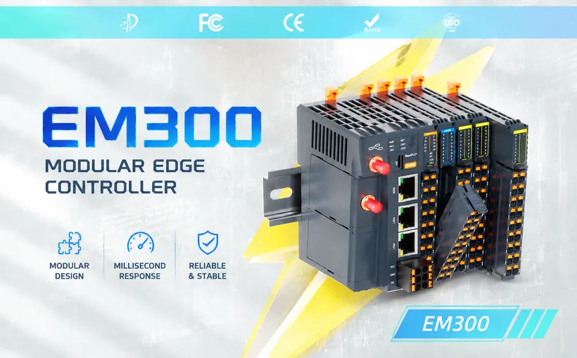
The EM300 Modbus to IEC104 Gateway is designed to simplify industrial protocol integration by overcoming the limitations of traditional gateways, including fixed I/O, separated control systems, complex application development, and high remote maintenance costs. It integrates six core capabilities into a single device: edge computing, visual programming, protocol conversion, industrial protocols, industrial networking, and scalable I/O.
Beyond Modbus-to-IEC104 conversion, the EM300 supports flexible IEC 60870-5-104 communication roles. It can operate as an IEC104 Server (slave/remote station) to provide field data to SCADA systems, dispatch centers, and Energy Management Systems (EMS), or as an IEC104 Client (master) to communicate with IEC104-compatible devices and systems.
In a typical Modbus-to-IEC104 application, the EM300 collects data from Modbus RTU/TCP devices on the field side and maps the acquired variables to IEC104 information objects through its built-in IEC104 Server node. The converted data can then be accessed by IEC104 clients, enabling seamless integration of existing Modbus devices into power automation and SCADA infrastructures.
Let’s walk through the steps to configure the EM300 as an IEC104 Server for Modbus-to-IEC104 integration, including gateway configuration, IEC104 point mapping, and communication testing.
Step 1: Prepare the Gateway and Field Data
Before configuring the IEC104 Server, make sure the required data points and communication environment are ready.
1.1 Preparation Requirements
Engineers should first confirm the data points that need to be collected and uploaded to the IEC104 system, including:
- Tele-signaling points
- Telemetry points
- Tele-control points
- Tele-regulation points
Connect the industrial gateway to the same local network as the IEC104 client/host system.
The typical communication architecture is:
Field Devices
(Modbus RTU/TCP)
        ↓
EM300 Industrial Edge Controller
        ↓
IEC104 Server
        ↓
SCADA / IEC104 Client
1.2 Connect the Gateway
This article provides detailed instructions on how to connect the EM series edge controller.
Step 2: Configure the EM300 IEC104 Server Node
After completing the gateway network configuration, enter the Visual Programming interface. (Click the “NODE-RED” button in the top-right corner of the page).
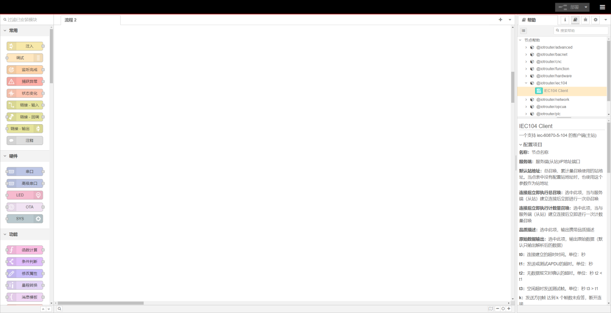
Add the IEC104 Server node and configure the required communication parameters and point table.
Step3: Configure the IEC104 Server node
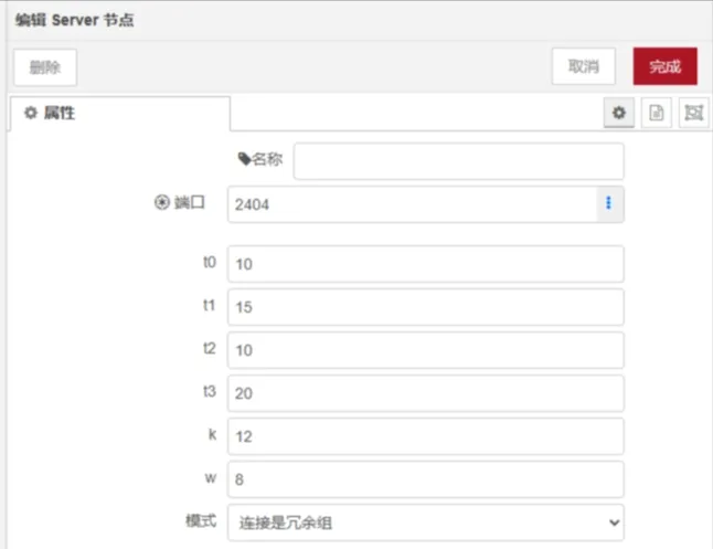
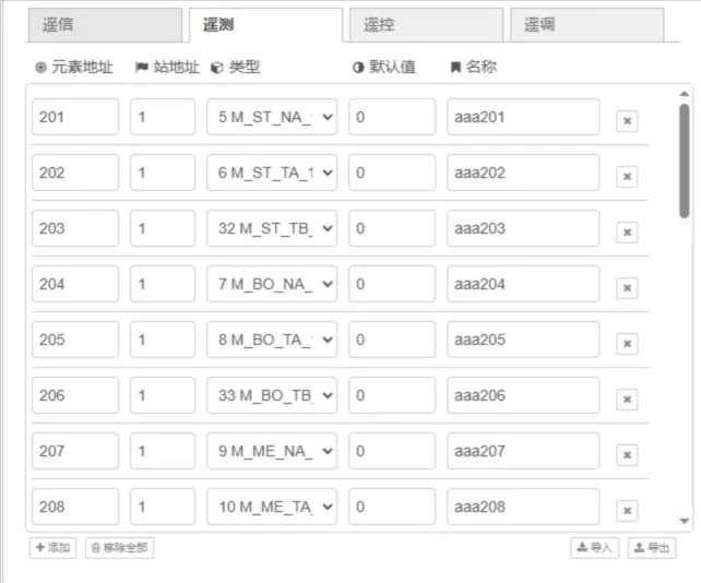
Select the IEC104 Server node, then configure the required parameters and point mappings.
Step4: Deploy and Test
Inject – Write Data
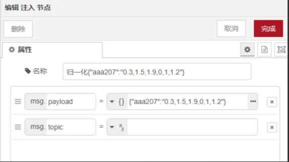
View Output
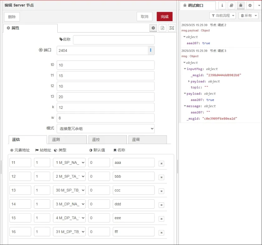
IEC104 Server Node Configuration Reference
1. Configuration Parameters Description
| Parameter | Description |
|---|---|
| Name | The name displayed for the node in the flow. |
| Port | The listening port of the IEC104 server. |
| t0 | Timeout for establishing a connection. Unit: seconds. |
| t1 | Timeout for sending or testing APDU frames. Unit: seconds. |
| t2 | Timeout for acknowledgement when no data messages are received. Unit: seconds. t2 < t1 |
| t3 | Idle timeout for sending test frames. Unit: seconds. t3 > t1 |
| k | Maximum number of unacknowledged [I] frames allowed before the sender disconnects the connection. |
| w | Number of received messages before the receiver sends an [S] frame acknowledgement. |
| Mode | Server/Slave mode. “Connection is Redundant Group” supports multiple connections. |
| Periodic Report | Data points with the “Periodic” option enabled will periodically report telemetry and status data to the IEC104 client according to this interval. |
| Spontaneous Report | Supports reporting triggered by value changes, parameter updates, and quality changes. |
| Log (Debug Only) | Used only for debugging purposes. |
| Remote Control/Adjustment Output Value Only | When enabled, only the value of remote control and adjustment commands is output. Otherwise, the output is in array format. |
2. Point Table
The point table can be used to quickly update the telemetry and status data of the IEC104 server (slave).
| Field | Description |
|---|---|
| IOA (Information Object Address) | The data point address stored in the server (slave). |
| COA (Common Address) | The common address of the IEC104 station. |
| Name | A custom name for the data point. It cannot be empty and must be unique. The name is used as the output key. Example: msg.payload.a = true, where a is the custom name. |
| Type | Data point type. |
Note:
- The IOA address can be duplicated, but the data type must be the same.
Example:
If ioa=1, type=1 already exists in the point table, adding ioa=1, type=2 again will cause an error.
If the configuration is forcibly saved, the server will discard the data point ioa=1, type=2.
- The IEC104 server (slave) only stores remote control and remote adjustment points. It does not store command values.
- Clock synchronization is supported.
3. Input
The node supports inputting point values in the following formats:
- Supports inputting point values in Number format.
- Supports inputting point values in Array format. The server will parse the values according to the array order. Refer to the following tables for the value order of each data type.
Example
Write
msg.payload.a = 0or
msg.payload.a = "1,0,0,0,0"or
msg.payload.a = [1,0,0,0,0]Read
msg.payload.a = nullor
msg.payload.a = [null,null,null,null,null]
For more information, please contact technical support.
Why Choose EM300 as Your Modbus to IEC 104 Gateway
When selecting an industrial protocol conversion gateway, the EM300 Series stands out for power automation projects with the following advantages:
1. All-in-One Integration — Lower System Costs
The EM300 integrates six core functions—edge computing, visual programming, protocol conversion, industrial protocols, industrial routing, and scalable I/O—into a single device. One unit handles protocol conversion, data acquisition, remote operations, and I/O control, eliminating the need for separate PLCs, routers, or industrial PCs. This significantly reduces system integration costs and project delivery timelines.
2. No PLC Programming Required — Drag-and-Drop Rapid Development
The EM300 features a deeply customized Node-RED visual programming tool. The entire “acquisition-transmission-control” workflow can be completed by dragging and dropping nodes. Traditional solutions require PLCs or industrial PCs with specialized programming skills, while the EM300’s visual workflow lets engineers complete configurations without writing code—dramatically shortening project delivery cycles.
3. Rich Protocol Library — Ready to Use Out of the Box
The EM300 comes with a comprehensive built-in industrial protocol library, covering Modbus RTU/TCP, OPC UA, BACnet, IEC104, IEC61850*, DLT645, HJ212, CJ188, and other mainstream industrial and power communication protocols. Whether it’s power meters, PLCs, or smart electricity meters, all can be quickly integrated.
4. Industrial-Grade Reliability — Built for Harsh Environments
The EM300 is designed to industrial standards with a -40°C to 85°C wide operating temperature range and hardware watchdog protection. It also supports automatic reconnection on network failure and intelligent data retransmission, along with optional UPS power failure protection supporting data buffering, parameter snapshots, and safe shutdown—minimizing data loss risks from unexpected power outages.
5. Flexible I/O Expansion
The EM300 comes standard with 4x isolated RS485, 2x isolated DI, and 2x isolated DO, while supporting up to 16 I/O expansion modules including digital input/output modules, relay output modules, and analog input/output modules. The plug-and-play distributed I/O architecture supports millisecond-level control response, meeting local control requirements in substation and power distribution scenarios.
6. Remote Operations — Improved Maintenance Efficiency
With IOTROUTER’s remote operations software IOTClient, the EM300 supports remote configuration, remote debugging, remote diagnostics, and remote firmware updates. It also supports VPN, firewall, and cross-site device networking, with intranet penetration and P2P direct connection technologies making remote device access as smooth as local operation.
7. Flexible Data Read/Write Methods
The EM300 supports both K-V key-value pair and object injection data read/write modes, flexibly adapting to different SCADA system integration requirements, while supporting the complete IEC104 communication flow including general interrogation and clock synchronization.
FAQs
Q: Can Modbus devices directly connect to IEC 104 systems?
No. Modbus and IEC104 are fundamentally different industrial communication protocols with distinct data models, message structures, and communication mechanisms. A protocol conversion gateway (such as the EM300) is required to enable interoperability.
Q: What is a Modbus to IEC 104 gateway?
A Modbus to IEC104 gateway is an industrial protocol conversion device that acquires data from Modbus RTU/TCP devices and converts it to IEC 60870-5-104 format for use by SCADA systems, dispatch centers, Energy Management Systems (EMS), and power monitoring platforms.
Q: Does IEC 104 support TCP/IP?
Yes. IEC 60870-5-104 is specifically designed as a telecontrol protocol for TCP/IP networks, making it well-suited for modern Ethernet-based SCADA and dispatch center communications.
Q: What is the default port for IEC 104?
The default TCP port for IEC 60870-5-104 is 2404. This is the port the EM300 IEC104 Server node listens on by default.
Q: Does the EM300 support both cyclic and spontaneous reporting?
Yes. The EM300’s IEC104 Server node supports both cyclic (periodic) reporting and spontaneous reporting (triggered by data changes, parameter updates, or quality changes), meeting the real-time and reliability requirements of power telecontrol systems.
Q: What industries use Modbus to IEC104 conversion?
Primary application industries include: power generation and transmission/distribution, substation automation systems, renewable energy (solar/wind), smart grid, factory power management, and building energy management (EMS)—any scenario requiring field device integration into power remote monitoring systems.
Summary
In just three steps—connect Modbus devices, configure the IEC104 Server point table, and deploy—the IOTROUTER EM300 Modular Industrial Edge Controller seamlessly bridges Modbus field devices with IEC104 power systems.
If you’re looking for a stable, easy-to-use Modbus to IEC 104 gateway for your power automation project, the IOTROUTER EM300 is worth a closer look.

Agnes Wang is an IoT Solutions Specialist at IOTRouter, focusing on industrial IoT gateways, edge computing, and industrial automation solutions.
She specializes in industrial communication technologies, including Modbus, IEC 60870-5-104, MQTT, OPC UA, PLC integration, and remote monitoring applications. She contributes to technical articles and application guides covering industrial IoT solutions, protocol conversion, and edge computing.