Greenhouse Automation with the Edge IoT gateway: Wiring, Logic, and What Actually Goes Wrong
This article describes how we’ve implemented Greenhouse Automation with the Edge IoT gateway.
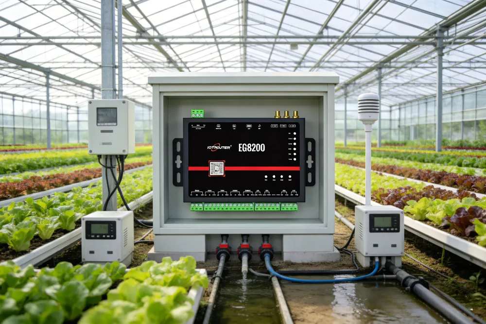
Working on greenhouse automation, the problem usually shows up in the same place.
Sensors are already installed. Fans and pumps are running. But nobody wired the two sides together. CO₂, temperature, humidity — each has its own display. The exhaust fan has its own controller. So does the pump. Someone ends up doing the coordination manually, watching alerts on a phone.
Had a tomato greenhouse like this — sensors in, fans still manual. After that, we just started putting the control logic on the gateway locally. Simpler, and it keeps working when the internet goes down.
How the Wiring Goes Together
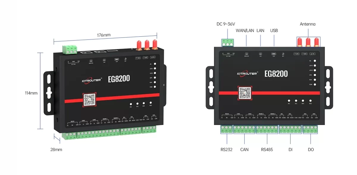
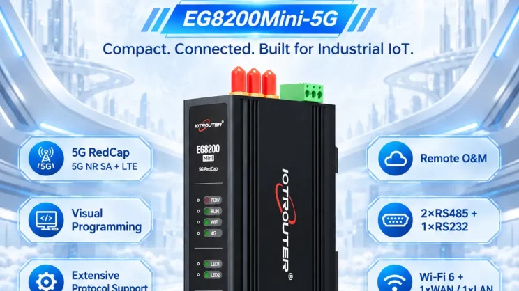
The EG8200 Edge IoT Gateway has two RS485 ports, both Modbus RTU. Most agricultural sensors already speak Modbus RTU, so they wire straight to the bus.
We usually split by sensor type — climate sensors on one bus, CO₂ and light on the other. Keeps address spaces separate and makes fault isolation easier later.
Some Modbus sensors ship with default addresses all set to 1. Worth setting addresses one device at a time before connecting to the shared bus. Some devices also don’t retain address settings properly after power loss — worth checking before deployment.
On the output side, two relay DOs. These switch an intermediate contactor coil; the contactor handles the motor load. For more than two devices, use RS485 relay expansion modules on the same bus.
DI ports for water level switches and door sensors. Useful for interlocks — side vents open, pad cooling pump stays off.
Termination Catches People Too
Had a site where temperature readings kept dropping out randomly. Wiring looked fine; configuration looked fine. Eventually found a long cable run at the end of the bus with no termination resistor. Put 120Ω at both ends, sorted.
That kind of problem doesn’t show up in the software. You have to go back to the physical layer.
Also worth checking if any relay modules or pump controllers on the same bus are generating noise — had one site where the pump relay was causing intermittent read failures on nearby sensors until we added some spacing and ferrite cores.
Control Logic
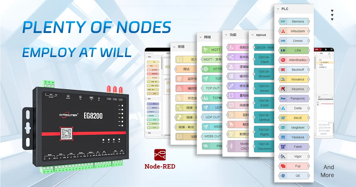
The EG8200 runs Node-RED on-device. Build flows in a browser, deploy, done. Setpoint needs changing on-site — open a browser, change the number, redeploy.
We poll sensors every 30 seconds or so. When the temperature goes above the threshold, DO1 triggers the exhaust fan contactor. Humidity drops, Modbus write tells the pump controller to run at partial output. Hysteresis is built in so the fan doesn’t keep toggling — has to drop a couple degrees below the trigger before it switches back off.
Runs entirely locally. Internet drops, greenhouse keeps going. When the connection comes back, buffered data uploads normally again.
For sites that already have SCADA — we usually go MQTT. We’ve used it with Mosquitto, HiveMQ, and AWS IoT without much trouble, though if the existing broker has custom authentication or topic rules, that’s where setup time actually goes.
The logic itself isn’t where the time goes. Wiring, device commissioning, and a lot of the commissioning time end up being tracing wiring and confirming which breaker feeds which fan — that’s where the hours actually go.
Auto and Manual
Automatic runs unattended. But crop transitions, maintenance, unexpected growing conditions — preset logic won’t always be right.
Manual mode is triggered from the local Node-RED Dashboard or via an MQTT command. Automatic logic pauses; the operator has direct control. Dashboard works in any browser on the local network; no app needed.
On sites with unreliable connectivity, not having to go through a cloud portal to change a setpoint matters more than you’d think.
Commissioning
For a typical setup, one person can get it running in a few hours. Most of that is wiring.
Put the EG8200 in AP mode for commissioning — it broadcasts its own local network; no need to get on the farm’s WiFi. Just connect and open Node-RED directly.
Multi-bay sites: close bays sometimes share one unit if the WiFi range works out. Separate structures usually get their own EG8200, each reporting via 4G. Some sites prefer running cable between buildings instead, depending on what’s already there.
Where It Makes Sense
Commercial vegetable and tomato greenhouses, hydroponic systems, seedling nurseries, cold storage. Anywhere control needs to keep running independently of internet connectivity.
Where it starts to hit limits: large sites with a lot of independently controlled zones. Two RS485 buses and two relay outputs cover most medium-scale setups. Beyond that, multiple units or different hardware.
A Few Questions That Come Up
Sensors from different manufacturers — will they work on the same bus?
Usually yes, as long as they support Modbus RTU. The thing to watch is baud rate — most default to 9600 8N1 but not all. If a sensor isn’t responding and wiring looks right, that’s the first thing to check.
Offline operation — how does it actually work?
All logic runs locally. Internet is only for data upload and remote access. Worth testing before leaving a site — disconnect the antenna, make sure everything behaves as expected.
Can the relay outputs switch motors directly?
Not directly. The relay switches a contactor coil; the contactor handles the motor. For more than two loads, add RS485 relay expansion modules.
Most of the problems on these projects end up being physical-layer stuff — termination, address conflicts, sensor placement. Once that’s sorted, the rest goes pretty quickly.
EG8200 specs and datasheet: product page. Questions: contact form.

Agnes Wang is an IoT Solutions Specialist at IOTRouter, focusing on industrial IoT gateways, edge computing, and industrial automation solutions.
She specializes in industrial communication technologies, including Modbus, IEC 60870-5-104, MQTT, OPC UA, PLC integration, and remote monitoring applications. She contributes to technical articles and application guides covering industrial IoT solutions, protocol conversion, and edge computing.