This guide explains how to connect a Siemens S7-200 PLC to the EG Edge Gateway via PPI protocol for industrial data communication. It is part of the PLC Integration Hub, focusing on real-world PLC connectivity with edge series gateways.
1. Conexión de hardware
Compatible PLC: S7-200
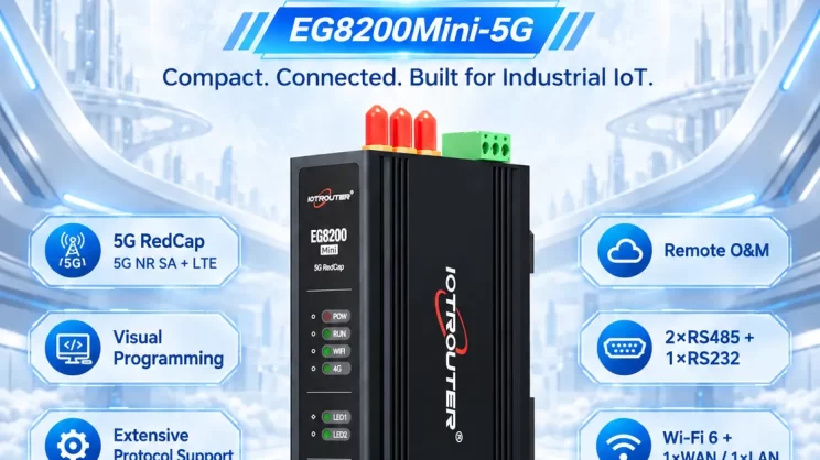
The Siemens S7-200 communicates via the PPI protocol. This section focuses on how the EG8200Mini reads data from the Siemens S7-200 PLC using the PPI protocol.
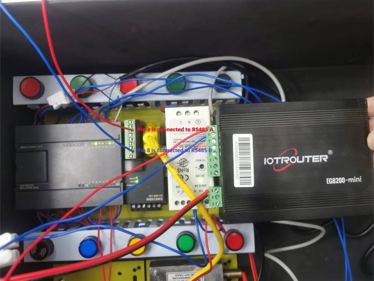
Before communication between the EG8200Mini and the Siemens S7-200, the wiring must be correct. The PPI protocol uses RS485 communication. The specific wiring is as follows: Pin 3 connects to A, and Pin 8 connects to B.
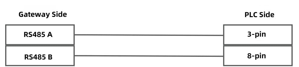
The actual wiring diagram is as follows: the red wire is RS485A connected to Pin 3 of the S7-200, and the blue wire is RS485B connected to Pin 8 of the S7-200.
2. PLC Serial Port Parameters
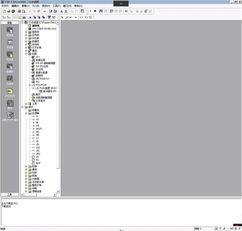
2.1. Open STEP7 Software
Open the STEP7 software.
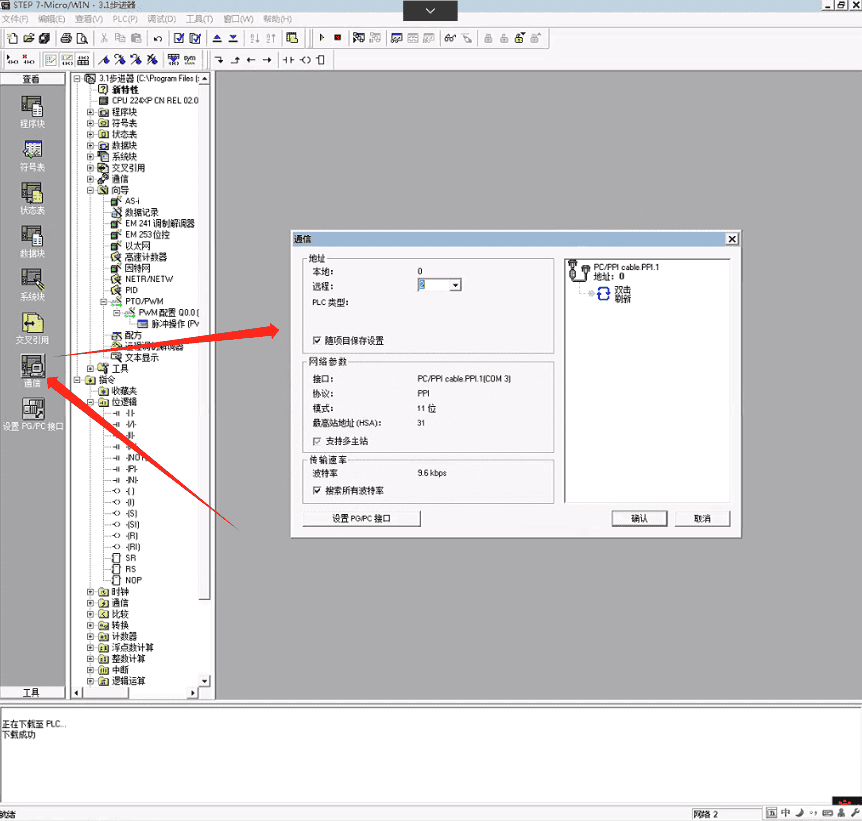
2.2. View Communication Parameters
You can see that the station address is 2 and the baud rate is 9600. These parameters will be required later for gateway configuration.
3. Configuración de la puerta de enlace
3.1. Configuración de la conexión del PLC
Drag a Siemens node from the left panel and double-click to open the settings page. Fill in the configuration according to the PLC serial parameters as follows:
Protocolo: Select PPI
Puerto serie: Select RS485-1 (choose according to actual hardware connection)
Velocidad en baudios: 9600
Bits de datos: 8
Bits de parada: 1
Paridad: INCLUSO
Tiempo de espera de comunicación: 2000
Serial Frame Interval: 100 ms (adjust according to actual conditions; recommended 50–100 ms)
Station Address: 2
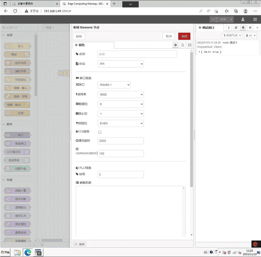
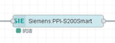
After completing the PLC connection settings, click Despliegue. The PLC status should display Ready.
3.2. Configuración de los puntos de datos
In general, you can fill in the data points to be read directly in the Siemens node parameter list. Once the data points are filled in, they will be read automatically according to the configured frequency.
In this example, an advanced method is used: reading PLC points via a function node. The advantage of this method is that the data points to be read can be dynamically modified.
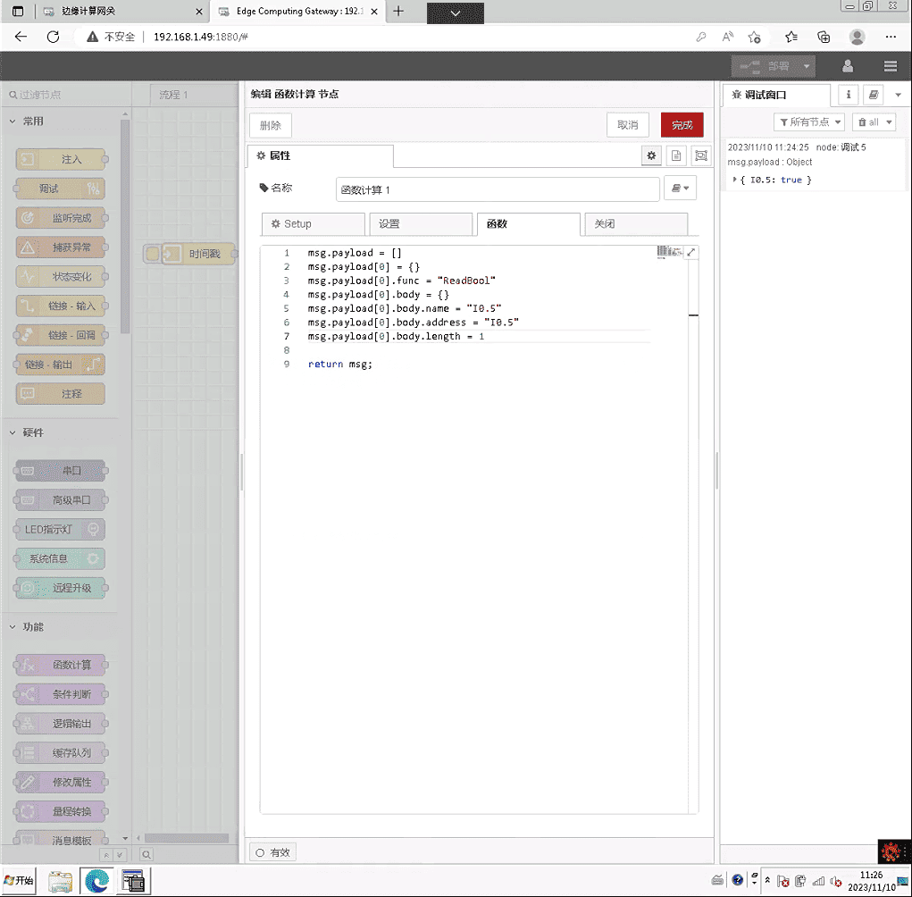
Drag a Function node and copy the following code:
The meaning of this code is: use the ReadBool method to read 1 Boolean value at address I0.5, and store the result in a variable named I0.5. The length parameter indicates how many consecutive addresses can be read at once. msg.payload is an array, so you can also read multiple different types of data at the same time.
All callable methods can be referred to in the node documentation:
This is a Yuque content card. Click the link to view:(Puedes utilizar Google Chrome para la traducción)
https://iotrouter.yuque.com/zn3vdn/eg8000/hh3gq8an371h7xiw
3.3. Pruebas
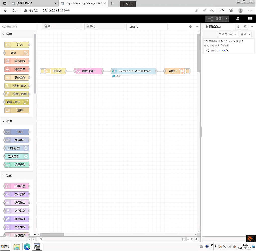
Drag an Inject node and a Debug node as shown in the diagram. Click the Inject node and observe the read data point. The result should be:
Guías relacionadas con la integración de PLC industriales
← Volver al Centro de integración de PLC

Agnes Wang es especialista en soluciones de IoT en IOTRouter, donde se dedica principalmente a las pasarelas de IoT industrial, la computación en el borde y las soluciones de automatización industrial.
Está especializada en tecnologías de comunicación industrial, entre las que se incluyen Modbus, IEC 60870-5-104, MQTT, OPC UA, integración de PLC y aplicaciones de monitorización remota. Colabora en la redacción de artículos técnicos y guías de aplicación sobre soluciones de IoT industrial, conversión de protocolos y computación periférica.