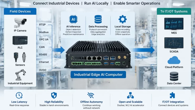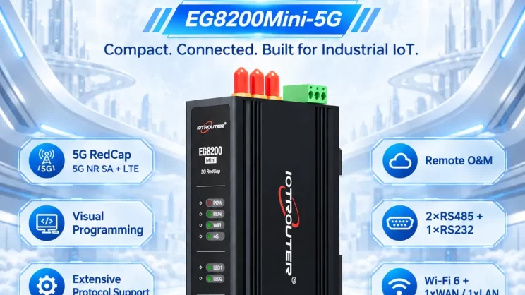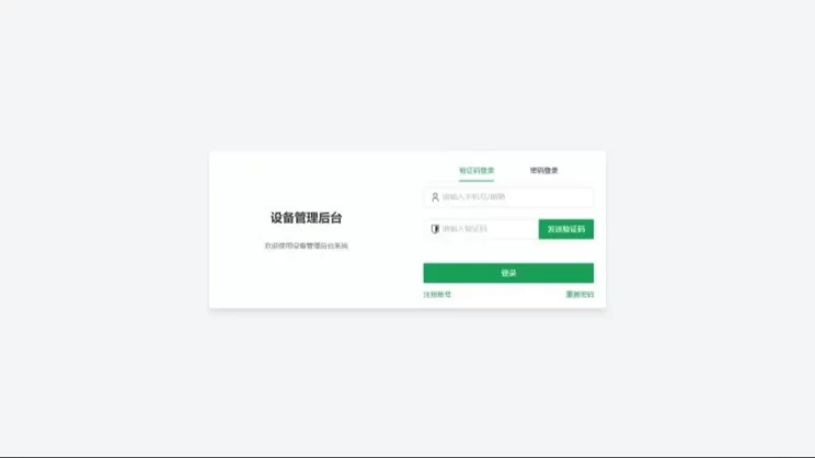
Guida allo sviluppo del computer industriale EC100 ARM – L’EC100 viene fornito con Node-RED 4.0 e NeuronEX-Lite già preinstallati, il che lo rende pronto all’uso per lo sviluppo di applicazioni edge fin dal primo momento.
Node-RED offre un'interfaccia di programmazione visiva di tipo "drag-and-drop" per la creazione rapida di logiche di business, mentre NeuronEX-Lite funge da piattaforma leggera di edge computing che supporta la connettività dei dispositivi con tempi dell'ordine dei millisecondi grazie alla compatibilità multiprotocollo. Questa combinazione semplifica notevolmente lo sviluppo e consente una rapida implementazione di soluzioni IoT industriali.
Preparazione allo sviluppo
1. Strumenti SSH
Consigliamo di utilizzare MobaXterm, oppure puoi scegliere il tuo programma preferito Strumento SSH.
2. Strumento di debug per porta seriale
Consigliamo di utilizzare XCOM oppure di scegliere il proprio gioco preferito strumento di debug per porte seriali.
3. Strumenti hardware
Tra gli strumenti di debug più comuni figurano: adattatori CAN-USB / adattatori 485-USB / cavi di rete, ecc. Si prega di provvedere autonomamente alla loro preparazione.
4. Catena di strumenti per la compilazione incrociata
Toolchain per la compilazione incrociata
Ambiente software
Sistema operativo: Linux embedded 20.04.1; ritagliato parzialmente
Node.js: v22.16.0
Python: python3.8
Shell: bash
GLIBC: 2.31
Interfacce periferiche
1. Porta seriale
L'EC100 è dotato di due ricetrasmettitori RS485 integrati.
| Interfaccia hardware | File del dispositivo |
|---|---|
| RS485-1 | /dev/ttyS4 |
| RS485-2 | /dev/ttyS3 |
Nota: Grazie alla trasmissione e alla ricezione RS485, gli utenti non devono preoccuparsi di passare dalla modalità di trasmissione a quella di ricezione, poiché l'hardware gestisce automaticamente questa operazione.
1.1. Test rapido
Per eseguire i test, utilizzare lo strumento minicom. Per istruzioni specifiche sull'utilizzo, effettuare una ricerca su Baidu o consultare DeepSeek.
1.2. Esempio di test del codice
#include

#include

#include

#include

#include

#include

#include

#include

#define BUFFER_SIZE 256

typedef struct {

int baud_rate; // Velocità di trasmissione

int data_bits; // Bit di dati (5, 6, 7, 8)

int stop_bits; // Bit di stop (1, 2)

char parity; // Parità (N: Nessuna, O: Dispari, E: Pari)

} SerialConfig;

int set_serial_attr(int fd, SerialConfig *config)

{

struct termios tty;

if (tcgetattr(fd, &tty) < 0) { perror("tcgetattr"); return -1; } // Imposta la velocità di trasmissione speed_t speed;

switch (config->baud_rate) {

caso 9600: velocità = B9600; break;

caso 19200: velocità = B19200; break;

caso 38400: velocità = B38400; break;

caso 57600: velocità = B57600; break;

caso 115200: velocità = B115200; break;

impostazione predefinita:

fprintf(stderr, "Velocità di trasmissione non supportata, si utilizzerà 115200\n");

velocità = B115200;

}

cfsetispeed(&tty, speed);

cfsetospeed(&tty, speed);

// Imposta i dati

bits tty.c_cflag &= ~CSIZE;

switch (config->data_bits) {

caso 5: tty.c_cflag |= CS5; break;

caso 6: tty.c_cflag |= CS6; break;

caso 7: tty.c_cflag |= CS7; break;

caso 8: tty.c_cflag |= CS8; break;

impostazione predefinita:

fprintf(stderr, "Bit di dati non supportati, si utilizzano 8\n");

tty.c_cflag |= CS8;

}

// Imposta i bit di stop

if (config->stop_bits == 2) {

tty.c_cflag |= CSTOPB; } else {

tty.c_cflag &= ~CSTOPB; }

// Imposta la parità

switch (config->parity) {

caso 'N':

caso 'n': tty.c_cflag &= ~PARENB; // Nessuna parità

interruzione;

caso 'O':

case 'o': tty.c_cflag |= PARENB; // Parità dispari

tty.c_cflag |= PARODD; break;

caso 'E':

case 'e': tty.c_cflag |= PARENB; // Parità pari

tty.c_cflag &= ~PARODD; break;

impostazione predefinita:

fprintf(stderr, "Parità non supportata, si utilizza N\n");

tty.c_cflag &= ~PARENB;

}

// Altre impostazioni

tty.c_cflag |= (CLOCAL | CREAD); // Abilita la modalità ricevente e locale

tty.c_cflag &= ~CRTSCTS; // Disabilita il controllo di flusso hardware

tty.c_lflag &= ~(ICANON | ECHO | ECHOE | ISIG); // Modalità di input grezza

tty.c_oflag &= ~OPOST; // Modalità di output non elaborata

tty.c_cc[VMIN] = 1; // Numero minimo di caratteri da leggere

tty.c_cc[VTIME] = 0; // Timeout di lettura (unità: 0,1 s)

if (tcsetattr(fd, TCSANOW, &tty) < 0) {

perror("tcsetattr");

return -1; }

return 0;

}

int main(int argc, char *argv[]) {

int fd;

char *nome_porta;

if (argc < 2) {

fprintf(stderr, "Uso: %s \n", argv[0]);

exit(EXIT_FAILURE);

}

portname = argv[1]; // Configurazione della porta seriale

SerialConfig config = { .baud_rate = 115200, // Velocità di trasmissione

.data_bits = 8, // Bit di dati

.stop_bits = 1, // Bit di stop

.parity = 'N' // Parità (N: Nessuna, O: Dispari, E: Pari)

};

fd = open(portname, O_RDWR | O_NOCTTY | O_NONBLOCK);

if (fd < 0) {

perror("open");

exit(EXIT_FAILURE);

}

if (set_serial_attr(fd, &config)) {

close(fd);

exit(EXIT_FAILURE);

}

printf("Test di eco della porta seriale in esecuzione su %s\n", portname);

printf("Configurazione: baud rate %d, bit di dati %d, bit di stop %d, parità %c\n", config.baud_rate, config.data_bits, config.stop_bits, config.parity);

printf("Premere Ctrl+C per uscire.\n");

fd_set readfds;

char buffer[BUFFER_SIZE];

int n;

while (1) {

FD_ZERO(&readfds);

FD_SET(fd, &readfds); // Attesa indefinita dei dati in arrivo (senza timeout)

if (select(fd + 1, &readfds, NULL, NULL, NULL) < 0) {

perror("select");

break; }

if (FD_ISSET(fd, &readfds)) {

n = read(fd, buffer, BUFFER_SIZE - 1);

if (n > 0) {

buffer[n] = '\0';

printf("Byte %d ricevuti: %s\n", n, buffer); // Restituisce i dati

write(fd, buffer, n); } else if (n < 0) {

if (errno != EAGAIN && errno != EWOULDBLOCK) {

perror("read");

interruzione;

}

}

}

}

close(fd);

return 0;

}
Compilazione: gcc rs485_example.c -o rs485_example
Prova di funzionamento RS485-1: ./rs485_example/dev/ttyS4
2. LED
L'EC100 è dotato di un totale di 4 spie luminose, 2 delle quali possono essere programmate dall'utente.
| Interfaccia hardware | Indice IO | Numero IO | Chip Group | Note |
|---|---|---|---|---|
| POW | / | / | / | LED di indicazione di alimentazione. |
| CORRI | 39 | GPIO1_A7 | gpiochip1 | Riservato al firmware interno; non programmabile dall'utente; lampeggia durante il normale funzionamento. |
| LED1 | 38 | GPIO1_A6 | gpiochip1 | Programmabile dall'utente. |
| LED2 | 36 | GPIO1_A4 | gpiochip1 | Programmabile dall'utente. |
Nota: l'indice IO viene calcolato in base al numero IO.
2.1. Test rapido
#!/bin/bash

# Verifica se è stato specificato un indice GPIO
if [ -z "$1" ]; then
echo "Uso: $0 "
exit 1
fi

GPIO=$1
GPIO_PATH="/sys/class/gpio/gpio$GPIO"
EXPORT_PATH="/sys/class/gpio/export"

# Verifica se il GPIO è già stato esportato
if [ ! -d "$GPIO_PATH" ]; then
echo "Esportazione del GPIO $GPIO..."
echo "$GPIO" > "$EXPORT_PATH"
if [ $? -ne 0 ]; then
echo "Impossibile esportare il GPIO $GPIO. Controllare i permessi o verificare se è in uso."
exit 1
fi
else
echo "Il GPIO $GPIO è già esportato."
fi

# Imposta la direzione del GPIO su uscita
echo "out" > "$GPIO_PATH/direction"

# Imposta il valore iniziale su basso
echo 0 > "$GPIO_PATH/value"

echo "Commutazione del GPIO $GPIO ogni 1 secondo. Premere Ctrl+C per interrompere."

# Avvia il ciclo di commutazione
while true; do
echo 1 >"$GPIO_PATH/value"
sleep 1
echo 0 >"$GPIO_PATH/value"
sleep 1
done
Prova di funzionamento: bash led_example.sh 38
2.2. Esempio di test del codice
#include <stdio.h>
#include <stdlib.h>
#include <string.h>
#include <unistd.h>
#include <fcntl.h>
#include <sys/ioctl.h>
#include <linux/gpio.h>
#include <errno.h>
#define GPIO_CHIP "/dev/gpiochip1" // Use gpiochip1
#define GPIO_LINE 38%32 // Offset of the GPIO to control within chip1
#define PERIOD_US 500000 // Period time (microseconds)
int main() {
struct gpiohandle_request req;
struct gpiohandle_data data;
int fd, ret;
// Open the GPIO character device
fd = open(GPIO_CHIP, O_RDWR);
if (fd < 0) {
perror("Failed to open GPIO device");
return EXIT_FAILURE;
}
// Configure GPIO request
memset(&req, 0, sizeof(req));
req.lineoffsets[0] = GPIO_LINE; // GPIO line number
req.flags = GPIOHANDLE_REQUEST_OUTPUT; // Set as output mode
req.default_values[0] = 0; // Initial value set to low
strcpy(req.consumer_label, "gpio-toggle"); // Consumer label
req.lines = 1; // Number of GPIO lines to control
// Request GPIO control
ret = ioctl(fd, GPIO_GET_LINEHANDLE_IOCTL, &req);
if (ret < 0) {
perror("Failed to get GPIO handle");
close(fd);
return EXIT_FAILURE;
}
// Close GPIO character device (we already have line handle)
close(fd);
printf("Controlling GPIO chip1 line %d, period %.1f seconds...\n", GPIO_LINE, PERIOD_US/1000000.0);
// Periodically toggle GPIO level
while (1) {
data.values[0] = 1; // High level
ret = ioctl(req.fd, GPIOHANDLE_SET_LINE_VALUES_IOCTL, &data);
if (ret < 0) {
perror("Failed to set GPIO high level");
break;
}
usleep(PERIOD_US/2);
data.values[0] = 0; // Low level
ret = ioctl(req.fd, GPIOHANDLE_SET_LINE_VALUES_IOCTL, &data);
if (ret < 0) {
perror("Failed to set GPIO low level");
break;
}
usleep(PERIOD_US/2);
}
// Close GPIO line handle
close(req.fd);
return EXIT_SUCCESS;
}
Compilazione: gcc led_example.c -o led_example
Prova di funzionamento: ./esempio_led
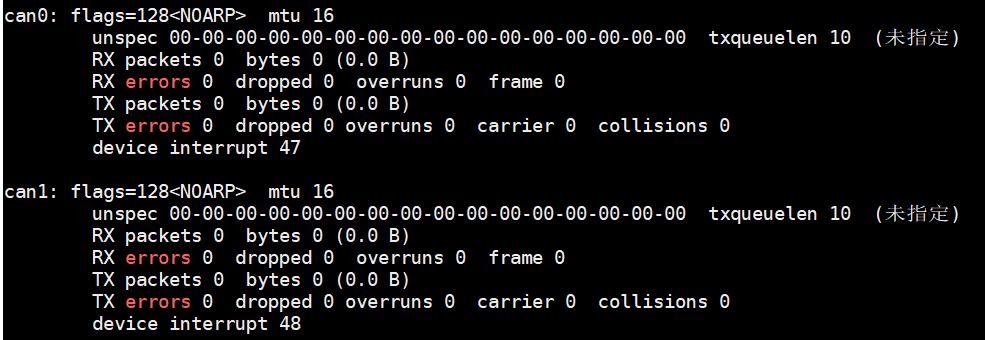
3. CAN FD
L'EC100 dispone di due interfacce CAN ad alta velocità
| Interfaccia hardware | Interfaccia di rete |
|---|---|
| CAN1 [H1 L1] | can0 |
| CAN2 [H2 L2] | can1 |
3.1. Test rapido
Collegare can0 e can1, test da riga di comando:
#Inizializzare prima can0 e can1, selezionare la velocità di trasmissione di 500k, utilizzare canfd, quindi selezionare can0 per ricevere i dati e can1 per inviarli

ip link set can0 down

ip link set can1 down

ip link set can0 type can bitrate 500000 sample-point 0.8 dbitrate 2000000 sample-point 0.8 fd on

ip link set can1 type can bitrate 500000 sample-point 0.8 dbitrate 2000000 sample-point 0.8 fd on

ip link set can0 up

ip link set can1 up

echo 4096 > /sys/class/net/can0/tx_queue_len

echo 4096 > /sys/class/net/can1/tx_queue_len

candump can0 &

cansend can1 001234EF#00.11.22.33.44.55.66.77
3.2. Esempio di test del codice
#include <stdio.h>
#include <stdlib.h>
#include <string.h>
#include <unistd.h>
#include <net/if.h>
#include <sys/ioctl.h>
#include <sys/socket.h>
#include <linux/can.h>
#include <linux/can/raw.h>
#include <fcntl.h>
#include <errno.h>
#include <stdint.h>

#define CAN_INTERFACE "can0"
#define BITRATE 500000
#define DATA_BITRATE 2000000
#define SAMPLE_POINT 0.8
#define TX_QUEUE_LEN 4096

// Configure CAN FD interface
int setup_can_fd_interface(const char *ifname) {
char cmd[512];
FILE *fp;

// Bring the interface down
snprintf(cmd, sizeof(cmd), "ip link set %s down", ifname);
system(cmd);

// Set CAN FD parameters
snprintf(cmd, sizeof(cmd),
"ip link set %s type can bitrate %d sample-point %.1f "
"dbitrate %d dsample-point %.1f fd on",
ifname, BITRATE, SAMPLE_POINT, DATA_BITRATE, SAMPLE_POINT);
if (system(cmd) != 0) {
fprintf(stderr, "Failed to configure CAN FD interface %s\n", ifname);
return -1;
}

// Set TX queue length
snprintf(cmd, sizeof(cmd), "/sys/class/net/%s/tx_queue_len", ifname);
fp = fopen(cmd, "w");
if (fp == NULL) {
perror("Failed to open tx_queue_len");
return -1;
}
fprintf(fp, "%d", TX_QUEUE_LEN);
fclose(fp);

// Bring the interface up
snprintf(cmd, sizeof(cmd), "ip link set %s up", ifname);
if (system(cmd) != 0) {
fprintf(stderr, "Failed to bring up CAN interface %s\n", ifname);
return -1;
}

printf("CAN FD interface %s configured:\n", ifname);
printf(" Bitrate: %d\n", BITRATE);
printf(" Data bitrate: %d\n", DATA_BITRATE);
printf(" Sample point: %.1f\n", SAMPLE_POINT);
printf(" TX queue length: %d\n", TX_QUEUE_LEN);

return 0;
}

// Send a CAN FD frame
int send_can_fd_frame(int sock, uint32_t can_id, uint8_t *data, uint8_t len) {
struct canfd_frame frame;

memset(&frame, 0, sizeof(frame));
frame.can_id = can_id;
frame.len = len;
memcpy(frame.data, data, len);
frame.flags = CANFD_BRS; // Enable bit rate switching

int nbytes = write(sock, &frame, sizeof(frame));
if (nbytes != sizeof(frame)) {
perror("CAN FD frame send failed");
return -1;
}

printf("Sent CAN FD frame: ID 0x%08X, data: ", can_id);
for (int i = 0; i < len; i++) {
printf("%02X ", data[i]);
}
printf("\n");

return 0;
}

// Receive CAN messages (supports classic CAN and CAN FD)
void receive_can_messages(int sock) {
struct canfd_frame frame;
int nbytes;

printf("Starting to receive CAN messages (Ctrl+C to stop)...\n");

while (1) {
nbytes = read(sock, &frame, sizeof(frame));
if (nbytes < 0) {
if (errno == EAGAIN || errno == EWOULDBLOCK) {
continue;
}
perror("CAN frame read failed");
break;

}

if (nbytes == CAN_MTU) {
// Classic CAN frame
printf("Received CAN frame: ID 0x%08X, DLC %d, data: ",
frame.can_id, frame.len);
}else if (nbytes == CANFD_MTU) {
// CAN FD frame
printf("Received CAN FD frame: ID 0x%08X, DLC %d, data: ",
frame.can_id, frame.len);
}else {

printf("Received frame with unexpected size %d\n", nbytes);
continue;
}

for (int i = 0; i < frame.len; i++) {
printf("%02X ", frame.data[i]);
}
printf("\n");
}
}

int main() {
int s;
struct sockaddr_can addr;
struct ifreq ifr;

// Configure CAN FD interface
if (setup_can_fd_interface(CAN_INTERFACE) < 0) {
return 1;
}

// Create socket
if ((s = socket(PF_CAN, SOCK_RAW, CAN_RAW)) < 0) {
perror("Socket creation failed");
return 1;
}

// Enable CAN FD support
int enable_canfd = 1;
if (setsockopt(s, SOL_CAN_RAW, CAN_RAW_FD_FRAMES, &enable_canfd, sizeof(enable_canfd)) < 0) {
perror("Failed to enable CAN FD support");
close(s);
return 1;
}

// Specify CAN interface
strcpy(ifr.ifr_name, CAN_INTERFACE);
if (ioctl(s, SIOCGIFINDEX, &ifr) < 0) {
perror("IOCTL SIOCGIFINDEX failed");
close(s);
return 1;
}

// Bind socket to CAN interface
addr.can_family = AF_CAN;
addr.can_ifindex = ifr.ifr_ifindex;
if (bind(s, (struct sockaddr *)&addr, sizeof(addr))< 0) {
perror("Bind failed");
close(s);
return 1;
}

// Send test CAN FD frame (ID 0x001234EF, data 00.11.22.33.44.55.66.77)
uint8_t test_data[] = {0x00, 0x11, 0x22, 0x33, 0x44, 0x55, 0x66, 0x77};
if (send_can_fd_frame(s, 0x001234EF, test_data, sizeof(test_data)) < 0) {
close(s);
return 1;
}

// Start receiving CAN messages
receive_can_messages(s);

close(s);
return 0;
}
Raccolta: gcc can_example.c -o can_example
Prova di funzionamento: ./esempio_can
4. Pulsanti
Pulsanti EC100: Programma interno occupato, utilizzato per il riavvio o il ripristino della configurazione relativa alla pagina web del dispositivo
Riavvio: Premere per 1 secondo e rilasciare
Reimposta + riavvia: Premere per più di 5 secondi
5. Watchdog hardware
Il watchdog hardware dell'EC100 è abilitato per impostazione predefinita ed è gestito dal programma interno.
Ciclo di monitoraggio: <30 secondi
Nota: se il programma interno viene interrotto, è necessario assumere manualmente il controllo del servizio di alimentazione del watchdog; in caso contrario, il dispositivo si riavvierà periodicamente.
6. Porte di rete
The network ports are divided into WAN and LAN ports, managed by the internal network program; configuration must be done via the web interface. For details, please refer to:
This is a Yuque content card, click the link to view: https://iotrouter.yuque.com/zn3vdn/ec/go5fnig7b5xumq79?singleDoc
7. Reti cellulari senza fili
The EC100 supports 4G communication (4G version); module identification and dialing are managed by the internal program, and users do not need to concern themselves with this. For details, please refer to:
This is a Yueque content card; click the link to view: https://iotrouter.yuque.com/zn3vdn/ec/go5fnig7b5xumq79?singleDoc
Applicazioni software
1. Programma di gestione interna
To simplify user experience, the EC100 is equipped with the built-in management program iotrouter, which automatically starts at boot. The management program includes, but is not limited to, the following functions:
- Device Initialization
- Network Management
- Watchdog
- Button Monitoring
- Firewall
- Device Configuration Service (default port 80; listening port can be changed; file: /usr/local/src/iotrouter/web/user-config.js)
- User File Browsing Function (default path /home; path can be changed; file: /usr/local/src/iotrouter/web/user-config.js)
Note: Internal programs must remain active; otherwise, the device may fail to boot normally. If users must disable internal management programs, they must take over the aforementioned management program services themselves.
2. NeuronEX
The EC100 is pre-installed with NeuronEX-Lite, which starts automatically at boot and listens on port 8085. For more details, see:
This is a Yuque content card; click the link to view: https://iotrouter.yuque.com/zn3vdn/ec/hdsb71i79vmfr8wd?singleDoc
- Check service status: systemctl status neuronex
- Riavvia il servizio: systemctl restart neuronex
- Sospensione del servizio: systemctl stop neuronex
- Disable service startup: systemctl disable neuronex
3. Node-RED
EC100 has built-in Node-RED, which starts automatically at boot and listens on port 1880. For more details, see:
This is a Yueque content card. Click the link to view: https://iotrouter.yuque.com/zn3vdn/ec/hdsb71i79vmfr8wd?singleDoc
- Check service status: systemctl status node-red
- Riavvia il servizio: systemctl restart node-red
- Sospensione del servizio: systemctl stop node-red
- Disable service auto-start: systemctl disable node-red
4. Programmi sviluppati dagli utenti
User programs are developed freely by users and run independently, but users must manage memory and storage space to avoid system abnormalities. Software can be added to the system’s auto-start method:
- /etc/rc.local
- servizio systemd
- /etc/init.d system
Our company also provides customized software development services. Please consult our sales staff if you have any needs.
Masterizzazione di immagini
When is image burning used? When using the device, users may accidentally delete system core files, incorrectly modify system configuration parameters (such as critical registry entries), or accidentally format the system partition, resulting in the system being unable to boot or functioning abnormally. In such cases, burning the system image for the corresponding device can quickly restore the system to its initial normal state.
1. Strumenti per la combustione
The burning toolkit is large; please contact technical support or sales to obtain it.
Driver: Driver
Tool: Burning tool
*.img: Factory image

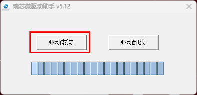
2. Installazione dei driver
Install: \DriverDriverInstall.exe
3. Combustione
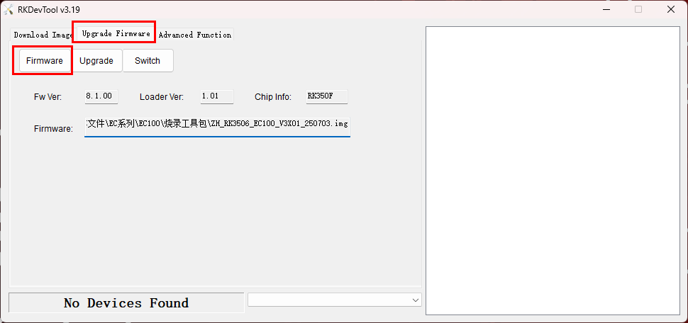
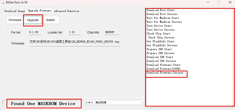
- Open \tool\RKDevTool.exe.
- Click Upgrade Firmware to jump to the burning interface.
- Click Firmware to select the image.
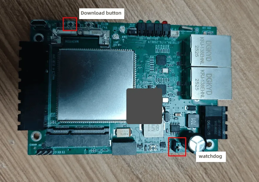
Short-circuit the watchdog of EC100 (the watchdog must be short-circuited during the burning process; the device will restart indefinitely).
Press and hold the download button to power up EC100.
When burning, “Found One MASKROM Device” will appear below, indicating that the device has been recognized.
Click “Upgrade” to start burning, and the burning log will appear in the log window on the right.
The last line will show “Success”, indicating that the burning was successful.

Agnes Wang è una specialista in soluzioni IoT presso IOTRouter, dove si occupa principalmente di gateway IoT industriali, edge computing e soluzioni di automazione industriale.
È specializzata in tecnologie di comunicazione industriale, tra cui Modbus, IEC 60870-5-104, MQTT, OPC UA, integrazione di PLC e applicazioni di monitoraggio remoto. Collabora alla stesura di articoli tecnici e guide applicative riguardanti soluzioni IoT industriali, conversione di protocolli ed edge computing.