In this tutorial, we will focus on explaining how the EG8200 Mini-CNC Gateway interfaces with Siemens CNC systems. We hope this proves helpful to you.
Starting today, we embark on a new journey. IOTRouter will launch a series of tutorials on how EG series gateways interface with CNC equipment. This tutorial series will feature case studies on well-known CNC brands such as Siemens, Mitsubishi, and many others.
1. EG8200 Mini-CNC Gateway
The EG8200Mini-CNC is an CNC Data Acquisition Gateway designed for CNC equipment with powerful data acquisition and remote monitoring capabilities. The equipment supports a variety of industrial protocols, such as Modbus, MQTT, etc., and can be compatible with multi-brand CNC equipment to help users achieve remote CNC machine tool management.
2. Siemens CNC
Siemens CNC is a series of numerical control systems developed by Siemens. Through CNC systems, machine tools can precisely execute operations such as cutting, drilling, milling, and turning according to pre-programmed instructions (G-code/ISO code).
Siemens CNC systems are widely used in automotive, aerospace, mechanical manufacturing, mold processing, and other industries, offering high precision, high efficiency, and high reliability.
3. How to Interface the EG8200Mini-CNC gateway with Siemens CNC
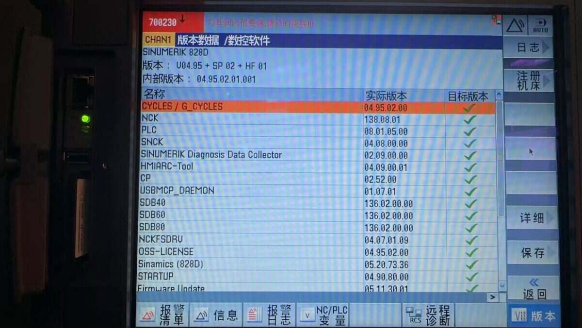
Compatible CNC: SINUMERIK 802/810/828/840
1. Hardware Connection
The Siemens CNC protocol utilizes Ethernet communication. Therefore, only ensure the gateway’s LAN port IP and the CNC’s IP are within the same subnet (Note: In special cases, they may be on different subnets, requiring routing configuration—consult technical support for details). IP addresses are assigned as follows in this example:
|
EG8200Mini-CNC gateway |
Siemens CNC |
|
| IP Address | 10.227.150.30 | 10.227.150.95 |
2. CNC Communication Parameters
Provided by the CNC engineer.
The CNC network port parameters are:
IP: 10.227.150.95, Port: 102
3. Gateway Settings
3.1. CNC Connection Settings
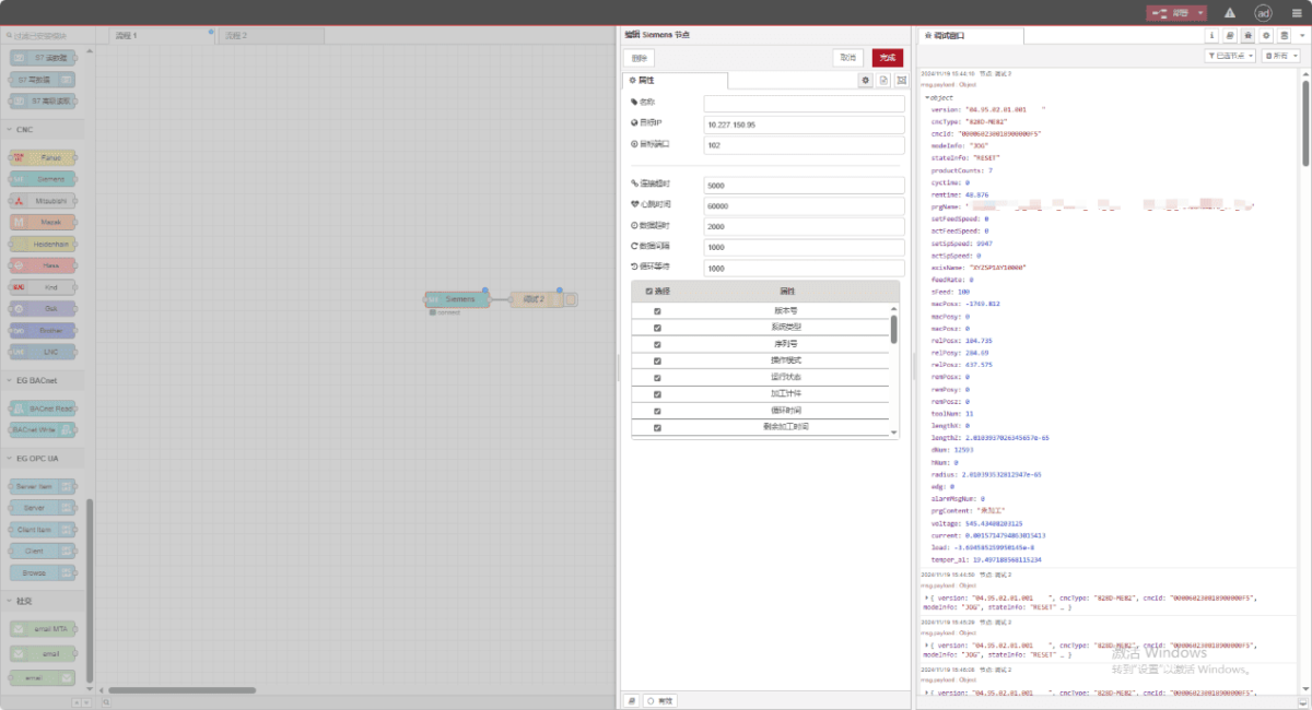
Drag a Siemens node from the CNC panel on the left. Double-click to open the settings page and configure as follows based on the PLC parameters:
Address: 10.227.150.95
Port: 102
Connection Timeout: 5000
Heartbeat Interval: 60000
Data Timeout: 2000
Data Interval: 1000 (Read Cycle)
Loop Wait: 1000 (Data Point Read Interval)
3.2. Data Point Settings
Check the required data:

3.3. Testing
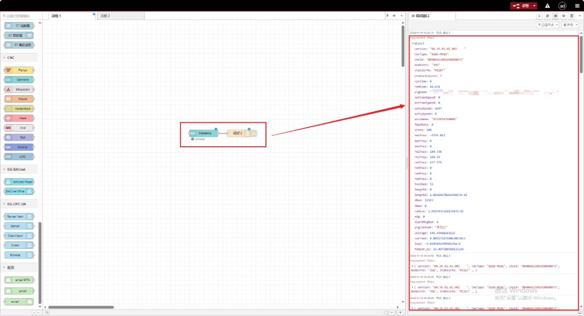
Click Deploy and observe a data point being printed every few seconds. Verify the received data points to confirm successful communication!
For the data point reference table, please refer to:
This is a Yueque content card. Click the link to view: https://iotrouter.yuque.com/zn3vdn/eg8000/xr6s46z90pevgwag
