What is serial communication? The academic explanation is a method of continuously sending one bit of data through the bus at a point in time. Just like an archer shooting his bow and arrow frequently, whoosh, whoosh, whoosh…
What is the serial communication protocol? To put it bluntly, it is the protocol transmission method used in serial communication.
How many types of serial communication protocols are there? Serial communication protocols include inter-system protocols and internal system protocols.
Intersystem Protocol: An intersystem protocol used to communicate between two different devices. Just like the communication between the computer and the microcontroller kit. Communication takes place via the internal bus system. Common ones include UART protocol, USART protocol, and USB protocol.
Internal System Protocol: The internal system protocol is used to communicate between two devices on the circuit board. While using these in-system protocols we will extend the peripherals of the microcontroller without using the in-system protocols. Using in-system protocols increases circuit complexity and power consumption. Using in-system protocols, circuit complexity and power consumption are reduced, costs are reduced, and access to data is very secure. Common ones include I2C protocol, SPI protocol, and CAN protocol.
Protocolo UART
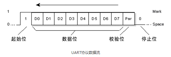
UART stands for Universal Asynchronous Transmitter and Receiver. The UART protocol is a serial communication with two wired protocols. Data cable signal lines are labeled Rx and Tx. Serial communication is commonly used to send and receive signals. It is transmitted and communicated with the serial port to receive data without pulse-like. The UART receives the data bytes and sends the individual bits sequentially.
El protocolo USAT se utiliza normalmente como periférico de MCU en sistemas embebidos; en general, el nivel TTL se deriva directamente del pin del chip; y el nivel RS232 puede conectarse al chip de conversión en el medio.Para más detalles, consulte: Estándares para la comunicación serie
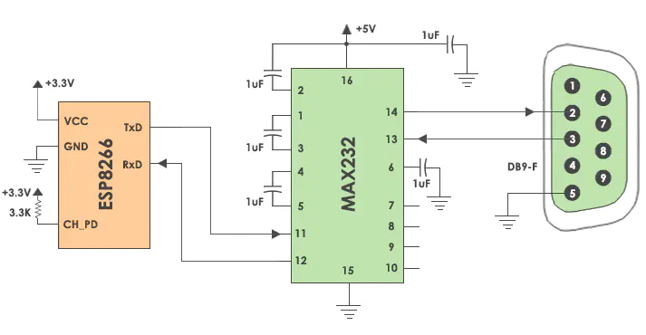
UART es un protocolo half-duplex. Half-duplex significa tener la capacidad de transmitir y recibir datos, pero no simultáneamente. La mayoría de los controladores tienen una UART hardware en la placa. Utiliza una línea de datos para enviar y recibir datos. Tiene un bit de inicio, un dato de 8 bits y un bit de parada, que indica que los datos de 8 bits se transmiten de alto a bajo. Por ejemplo: correo electrónico, mensajes de texto, walkie-talkies, servidor serie de equipos de transmisión IoT industrial.
Protocolo USART
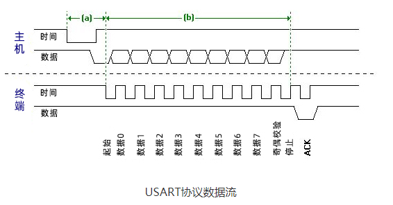
USART son las siglas de Universal Synchronous and Asynchronous Transmitter and Receiver. Se trata de una comunicación serie de protocolo de dos hilos. Las líneas de señal del cable de datos se denominan Rx y TX. Este protocolo se utiliza para enviar y recibir datos byte a byte junto con pulsos de reloj. Se trata de un protocolo full-duplex, lo que significa que los datos se envían y reciben simultáneamente a diferentes velocidades de la placa. Diferentes dispositivos se comunican con el microcontrolador a través de este protocolo. Por ejemplo, las telecomunicaciones.
Protocolo USB
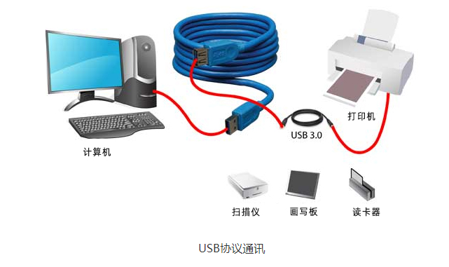
USB stands for Universal Serial Bus. Again, it is a two-wire protocol for serial communication. Data cable signal wires are marked D and D-. This protocol is used to communicate with system peripherals. The USB protocol is used to send and receive data serially to the host and peripheral devices. USB communication requires driver software based on system capabilities. USB devices can transmit data on the host without any requested bus. Now, most devices today use this technology to communicate with the USB protocol. Use USB to communicate with the ARM controller like a computer. USB transfers data in different modes. The first is a slow mode from 10 kbps to 100 kbps; the second is a full speed mode from 500kbps to 10mbps and a high speed mode from 25mbps to 400Mbps. The maximum USB cable length is 4 meters.
For example: mouse, keyboard, hub, switch, pen drive.
Protocolo I2C
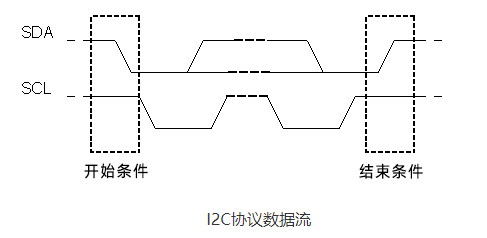
I2C stands for Inter Integrated Circuit. I2C requires only two wires to connect all peripherals to the microcontroller. I2C requires only two wires, SDA (serial data line) and SCL (serial clock line), to transfer information between devices. It is the master of the slave communication protocol. Each slave has a unique address. The master device sends the address and read/write flags of the target slave device. This address matches any slave device that is turned on, the remaining slave devices are in disabled mode. Once the addresses match, communication takes place between the master and that slave, and data is sent and received. The transmitter sends 8 bits of data and the receiver replies with 1 bit of confirmation. After the communication is completed, the master station issues a stop condition.
The I2C bus was developed by Philips Semiconductors. Its original purpose was to provide an easy way to connect the CPU to peripheral chips. Peripherals in embedded systems are often connected to the microcontroller as memory mapped devices. I2C requires only two wires to connect all peripherals to the microcontroller. These active lines, called SDA and SCL, are bidirectional. The SDA line is the serial data line, while the SCA line is the serial clock line.
I2C pull-up resistor:
Why use pull-up resistors in I2C SCL and SDA lines.
The SDA and SCL lines are both open-drain drivers.
It can drive the output low and drive it high.
In order for the line to go high, you must provide a pull-up resistor
Protocolo SPI
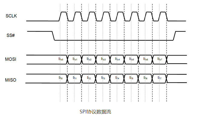
SPI son las siglas de Serial Peripheral Interface. Es uno de los protocolos de comunicación serie desarrollados por Motorola. A veces, el protocolo SPI también se denomina protocolo de 4 hilos. Requiere cuatro cables MOSI, MISO, SS y SCLK.El protocolo SPI se utiliza para comunicar dispositivos maestro y esclavo. El host configura primero el reloj con la frecuencia. A continuación, el host selecciona un dispositivo esclavo específico con el que comunicarse mediante un botón pull-tab. Selecciona ese dispositivo específico e inicia la comunicación entre el maestro y ese esclavo específico. El maestro sólo selecciona un esclavo a la vez. Se trata de un protocolo de comunicación full-duplex. En el caso de las transferencias de bits, no está limitado a palabras de 8 bits.
Protocolo CAN
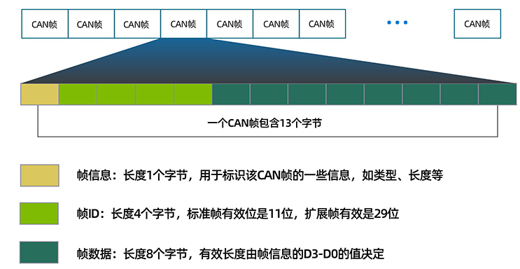
CAN son las siglas de Controller Area Network. Se trata de un protocolo de comunicación en serie. Requiere dos líneas CAN high (H) y CAN low (H-). Fue desarrollado por Robert Bosh Corporation en 1985 para su uso en redes de automoción. Se basa en un protocolo de transporte orientado a mensajes.
La década de los 70 fue la época en que los fabricantes de coches empezaron a introducir nuevas funciones, como el antibloqueo de frenos, el aire acondicionado, el control de marchas, el cierre centralizado de puertas, etc. Estas funciones requieren cableado adicional y diseños complejos, lo que aumenta los costes y los riesgos. Para superar estos problemas, Robert Bosch introdujo el protocolo CAN en los años ochenta. Este protocolo de comunicación en serie se estandarizó posteriormente como ISO11898 en 1993. Es el protocolo CAN el que ha transformado completamente la comunicación entre sensores avanzados.
El protocolo CAN se utiliza habitualmente en redes electrónicas de automóviles, aviones y sistemas médicos. Entre los productos más comunes se incluyen los equipos de CAN a Ethernet USR-CANET200
Palabras clave: 4gdtu