ET1010 Switching IO Expansion Module
- Switching the IO expansion module with 4 inputs and 4 relay outputs.
- Supports MODBUS RTU and plug-and-play cascading.
More details…
Description
ET1010 Switching IO Expansion Module supports Head-to-Tail Free Expansion of IO.
Adopting a unique head-to-tail cascade design, this means you can easily connect multiple modules together to form a powerful loop network.
-
Support MODBUS RTU protocol
-
Head-to-tail cascade design for easy expansion
-
Non-inductive expansion of IO interfaces
-
Plug-and-play, no configuration required
-
Adaptive master-slave station with adaptive register address
-
Communication delay in milliseconds, high-speed without packet loss
-
Real-time communication status indicated by hardware LEDs
-
Compatible with the ET3410 main device for optimal results


Datasheet
| RS485 | Number of ports | 1 way |
| Operating mode | Slave |
| Support baud rate | 115200/9600/4800/2400 |
| DO | Number of ports | 4 way |
| output type | Relay output |
| Relay capacity | 5A/30VDC 5A/250VAC |
| DI | Number of ports | 4 way |
| input type | NPN/PNP/dry contact |
| electrical characteristics | Optocoupler isolation |
| Electrical Parameters | Rated voltage | DC12V, working range DC12~24V |
| rated power | <1W |
| power protection | Anti-static, anti-surge, anti-reverse connection |
| Environmental Parameters | Operating temperature | -40~80℃ |
| storage temperature | -40~85℃ |
| environment humidity | 10-90% RH (non-condensing) |
| Mechanical Parameters | size | 80*71*63mm |
| weight | 150g |
| material | ABS |
Interface DESC
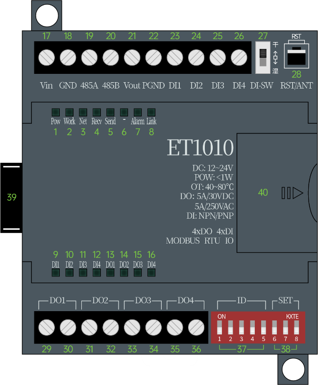
| No. | Name | Meaning | No. | Name | Meaning |
| 1 | Pow | Power indicator light, always on | twenty one | Vout | The positive pole of the external power supply, the voltage is equal to the input power supply voltage |
| 2 | Work | Working indicator light, 1 second strobe | twenty two | PGND | DI signal input isolation ground |
| 3 | Net | reserve | twenty three | DI1 | DI1 signal input |
| 4 | Recv | reserve | twenty four | DI2 | DI2 signal input |
| 5 | Send | reserve | 25 | DI3 | DI3 signal input |
| 6 | -- | reserve | 26 | DI4 | DI4 signal input |
| 7 | Alarm | Alarm indicator light, cascaded device communication is abnormal and always on | 27 | SW | Dry: Dry contact/PNP signal Wet: NPN signal |
| 8 | link | Connection indicator, cascaded device plugged in is always on | 28 | RST | reset button |
| 9 | DI1 | DI indicator | 29 | DO1 | Relay 1 output |
| 10 | DI2 | DI indicator | 30 | DO1 | Relay 1 output |
| 11 | DI3 | DI indicator | 31 | DO2 | Relay 2 output |
| 12 | DI4 | DI indicator | 32 | DO2 | Relay 2 output |
| 13 | DO1 | DO light | 33 | DO3 | Relay 3 output |
| 14 | DO2 | DO light | 34 | DO3 | Relay 3 output |
| 15 | DO3 | DO light | 35 | DO4 | Relay 4 output |
| 16 | DO4 | DO light | 36 | DO4 | Relay 4 output |
| 17 | Vin | Power input positive stage | 37 | Dial code | 1-5 means the MODBUS communication address, restart to take effect |
| 18 | GND | Power input negative | 38 | Dial code | 6-8 Set the baud rate, restart to take effect |
| 19 | 485A | RS485-A | 39 | M | M port, for upward cascading |
| 20 | 485B | RS485-B | 40 | S | S port, for cascading down |


