What is serial communication? The academic explanation is a method of continuously sending one bit of data through the bus at a point in time. Just like an archer shooting his bow and arrow frequently, whoosh, whoosh, whoosh…
What is the serial communication protocol? To put it bluntly, it is the protocol transmission method used in serial communication.
How many types of serial communication protocols are there? Serial communication protocols include inter-system protocols and internal system protocols.
Intersystem Protocol: An intersystem protocol used to communicate between two different devices. Just like the communication between the computer and the microcontroller kit. Communication takes place via the internal bus system. Common ones include UART protocol, USART protocol, and USB protocol.
Internal System Protocol: The internal system protocol is used to communicate between two devices on the circuit board. While using these in-system protocols we will extend the peripherals of the microcontroller without using the in-system protocols. Using in-system protocols increases circuit complexity and power consumption. Using in-system protocols, circuit complexity and power consumption are reduced, costs are reduced, and access to data is very secure. Common ones include I2C protocol, SPI protocol, and CAN protocol.
Protocole UART
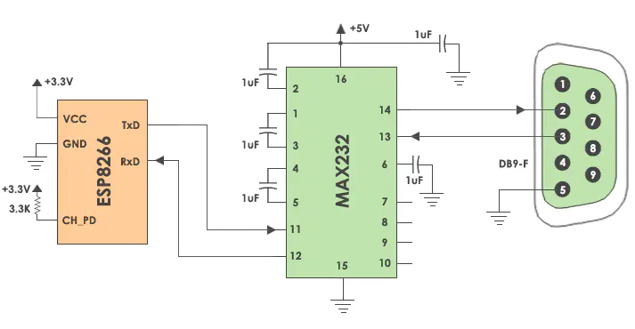
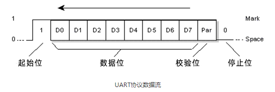
UART stands for Universal Asynchronous Transmitter and Receiver. The UART protocol is a serial communication with two wired protocols. Data cable signal lines are labeled Rx and Tx. Serial communication is commonly used to send and receive signals. It is transmitted and communicated with the serial port to receive data without pulse-like. The UART receives the data bytes and sends the individual bits sequentially.
USAT protocol is usually used as a peripheral of MCU in embedded systems; generally speaking, the TTL level is directly derived from the chip pin; and the RS232 level may be connected to the conversion chip in the middle.For details, please see: Standards for Serial Communication
UART est un protocole half-duplex. Half-duplex signifie qu'il est possible de transmettre et de recevoir des données, mais pas simultanément. La plupart des contrôleurs disposent d'un UART matériel sur la carte. Il utilise une ligne de données pour envoyer et recevoir des données. Il comporte un bit de départ, des données de 8 bits et un bit d'arrêt, indiquant que les données de 8 bits sont transmises de haut en bas. Par exemple : courrier électronique, messages textuels, talkies-walkies, équipement de transmission IoT industriel, serveur série.
Protocole USART
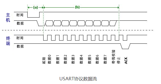
USART signifie Universal Synchronous and Asynchronous Transmitter and Receiver (émetteur et récepteur universel synchrone et asynchrone). Il s'agit d'un protocole de communication série à deux fils. Les lignes de signal du câble de données sont appelées Rx et TX. Ce protocole est utilisé pour envoyer et recevoir des données octet par octet avec des impulsions d'horloge. Il s'agit d'un protocole full-duplex, ce qui signifie que les données sont envoyées et reçues simultanément à des vitesses différentes. Différents dispositifs communiquent avec le microcontrôleur par le biais de ce protocole. Par exemple, les télécommunications.
Protocole USB
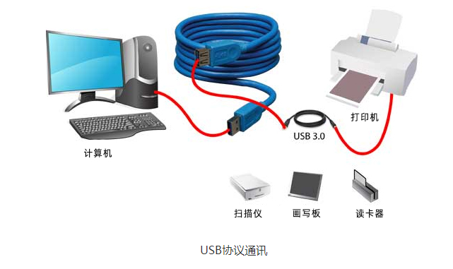
USB stands for Universal Serial Bus. Again, it is a two-wire protocol for serial communication. Data cable signal wires are marked D and D-. This protocol is used to communicate with system peripherals. The USB protocol is used to send and receive data serially to the host and peripheral devices. USB communication requires driver software based on system capabilities. USB devices can transmit data on the host without any requested bus. Now, most devices today use this technology to communicate with the USB protocol. Use USB to communicate with the ARM controller like a computer. USB transfers data in different modes. The first is a slow mode from 10 kbps to 100 kbps; the second is a full speed mode from 500kbps to 10mbps and a high speed mode from 25mbps to 400Mbps. The maximum USB cable length is 4 meters.
For example: mouse, keyboard, hub, switch, pen drive.
Protocole I2C
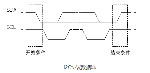
I2C stands for Inter Integrated Circuit. I2C requires only two wires to connect all peripherals to the microcontroller. I2C requires only two wires, SDA (serial data line) and SCL (serial clock line), to transfer information between devices. It is the master of the slave communication protocol. Each slave has a unique address. The master device sends the address and read/write flags of the target slave device. This address matches any slave device that is turned on, the remaining slave devices are in disabled mode. Once the addresses match, communication takes place between the master and that slave, and data is sent and received. The transmitter sends 8 bits of data and the receiver replies with 1 bit of confirmation. After the communication is completed, the master station issues a stop condition.
The I2C bus was developed by Philips Semiconductors. Its original purpose was to provide an easy way to connect the CPU to peripheral chips. Peripherals in embedded systems are often connected to the microcontroller as memory mapped devices. I2C requires only two wires to connect all peripherals to the microcontroller. These active lines, called SDA and SCL, are bidirectional. The SDA line is the serial data line, while the SCA line is the serial clock line.
I2C pull-up resistor:
Why use pull-up resistors in I2C SCL and SDA lines.
The SDA and SCL lines are both open-drain drivers.
It can drive the output low and drive it high.
In order for the line to go high, you must provide a pull-up resistor
Protocole SPI
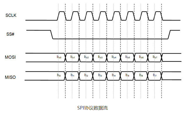
SPI stands for Serial Peripheral Interface. It is one of the serial communication protocols developed by Motorola. Sometimes the SPI protocol is also called a 4-wire protocol. It requires four wires MOSI, MISO, SS and SCLK.SPI protocol is used to communicate master and slave devices. The host first configures the clock with frequency. The host then selects a specific slave device to communicate with via a pull-tab button. Select that specific device and start communication between the master and that specific slave. The master selects only one slave at a time. It is a full-duplex communication protocol. In the case of bit transfers, it is not limited to 8-bit words.
Protocole CAN
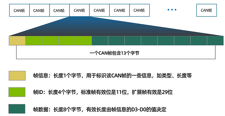
CAN est l'abréviation de "Controller Area Network" (réseau de contrôleurs). Il s'agit d'un protocole de communication série. Il nécessite deux lignes CAN high (H) et CAN low (H-). Il a été développé par Robert Bosh Corporation en 1985 pour être utilisé dans les réseaux automobiles. Il est basé sur un protocole de transport orienté message.
The 1970s was the era when car manufacturers started introducing new features such as anti-lock braking, air conditioning, gear control, centrally operated door locks, etc. These features ensure additional wiring and complex designs, increasing costs and risks. To overcome these problems, Robert Bosch introduced the CAN protocol in the 1980s. This serial communication protocol was further standardized as ISO11898 in 1993. It is the CAN protocol that has completely transformed communication between advanced sensors.
The CAN protocol is commonly used in electronic networks in automobiles, aircraft and medical systems. Common products include Can to Ethernet equipment USR-CANET200
Keywords: 4gdtu